Do you have a question about the Siemens FDM1101-Rx and is the answer not in the manual?
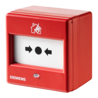
The FDM1101-Rx is a manual call point designed for manually triggering alarms in case of fire. It operates on a collective protocol, indicating its alarm status via a red LED. The device is available in several versions, including models with plastic or glass inserts, and specific versions for 'France'.
The primary function of the FDM1101-Rx is to allow individuals to manually initiate a fire alarm. When activated, it transmits a danger level '3' (Alarm/Fire) to the control panel. A danger level '0' signifies 'No danger' (Normal condition). The evaluation of these danger levels and subsequent actions (e.g., activation of remote transmission) are configured in the control panel.
The activation mechanism can be either a resettable plastic insert or a breakable glass insert. A key (FDMK295) is provided with each unit, serving a triple function: testing manual call points, resetting triggered manual call points, and unlocking the case to open the unit. An optional protective cover (FDMC295) can be used to prevent unintentional triggering of alarms.
The device features a red LED for alarm indication, visible through an optical fiber from the outside. In normal operation, the LED is off. When an alarm is triggered, the LED flashes at 1-second intervals or remains permanently on, depending on the control panel's configuration.
Detector Line:
Connections:
Environmental Conditions:
Mechanical Data:
Standards:
The FDM1101-Rx is designed for easy installation in accessible locations, typically at a height of 1.3 to 1.6 meters. For surface-mounted feed lines, optional back boxes (FDMH295-R or FDMH295-S) are available. The FDMH295-R has no pre-drilled holes, while the FDMH295-S has two holes with grommets for cables of Ø 5 mm.
Installation involves mounting the back box, connecting shielded detector line cables to a separate connection terminal (if applicable), and connecting the detector line wires to the device's four terminals. A control-panel specific Line Termination Element (EOL) must be connected at the end of each collective detector line. After wiring, the switching unit is secured, and the cover is refitted, ensuring the spring is tensioned with the plastic or glass insert.
A 'NOT IN USE' label is provided for manual call points that are deactivated, as deactivating them prevents alarms from being forwarded.
Function Check: The devices undergo an automatic performance check during self-test. However, regular on-site checks are recommended annually. Heavily soiled or damaged devices should be replaced. No other special maintenance is necessary.
Testing Detector with the Key: The manual call point can be tested using the provided key (FDMK295). Before testing, the manual call point should be switched to 'Test' mode on the control panel to prevent false alarms. To test, insert the key until the switching unit moves, triggering the call point. To re-arm, pull out the key, which returns the switching unit to a straight, armed position.
Replacing Broken Glass Insert: If a glass insert is broken, it can be replaced. The glass insert is covered by a foil layer to hold splinters together for safe removal. To replace:
Spare parts, including different types of plastic and glass inserts, protective covers, back boxes, metal cable glands, and connection terminals, are available as optional accessories.
| Brand | Siemens |
|---|---|
| Model | FDM1101-Rx |
| Category | Safety Equipment |
| Language | English |