Do you have a question about the Siemens LME71 Series and is the answer not in the manual?
General warnings to prevent injury, damage, or environmental impact.
Guidelines for correctly mounting the unit to ensure safety and reliability.
Critical instructions for proper electrical and mechanical installation.
Best practices for connecting flame detectors to ensure signal integrity.
Essential checks and procedures before starting up the system.
Overview of applicable directives, standards, and certifications.
Information on the designed lifetime and replacement recommendations.
Guidelines for environmentally sound disposal of the unit.
Explanation of symbols and formatting used in the document.
Key features and capabilities of the LME7 burner control system.
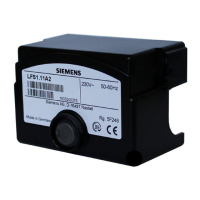
Summary of different burner control models and their features.
Details on program modules, including voltage variants and burner types.
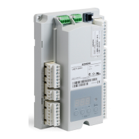
Description of optional external displays and operating units.
Summary of different flame detector types compatible with LME7.
Overview of compatible electromotoric actuators for control.
Information on the pressure switch used for monitoring.
Details on dummy plugs for RJ11 connectors.
Listing of connector sets and their article numbers.
Description of service tools like OCI410 and ACS410.
Essential technical specifications for the LME7 basic unit.
Electrical ratings and specifications for all input terminals.
Electrical ratings and specifications for all output terminals.
Maximum permissible cable lengths for various terminals.
Technical data for actuator connections and ratings.
Guidelines for selecting appropriate cable cross-sectional areas.
Mechanical and electrical data for RAST5 connectors.
Mechanical and electrical data for RAST3.5 connectors.
Specifications for the AGV50 signal cable.
Information on the dummy plug for RJ11 connectors.
Operating, storage, and transport environmental conditions.
Technical details for various flame detectors including ionization and QRA types.
Conditions required for a successful burner startup sequence.
Behavior and safety shutdown due to undervoltage conditions.
How the system handles intermittent operation and automatic shutdowns.
Response of the control system to various fault conditions.
Procedure for resetting the LME7 after a lockout.
Rules governing restarts after flame loss or during safety time.
Overview of the main operating elements and diagnostic choices.
How operating states are indicated via multicolor signal lamp.
Procedure for diagnosing fault causes using LEDs and interface.
Connection diagram for the LME71 using AGG9 connector.
Connection diagram for the LME72 using AGG9 connector.
Connection diagram for the LME73 using AGG9 connector.
Basic overview of LME7 inputs and outputs.
Details on digital inputs such as safety loop, external controller, and pressure switches.
Key parameters related to actuator control and modulation.
Compatible actuators and their operating modes.
Explanation of the internal program cycle time and operation.
Input signals for load controllers, including step and analog types.
How to achieve multistage/modulating mode using a 3-position step input.
Modulating mode using analog input signals.
Setting the dead band for modulating control to prevent hunting.
Practical examples and limitations for different applications.
Identification and function of buttons and display elements on the AZL2.
Interpretation of various symbols shown on the AZL2 display.
Description of special functions like manual lockout.
General operation, normal display, startup/shutdown, and fault displays via AZL2.
How to navigate through different menu levels using buttons.
Accessing and displaying information via the info level.
Accessing and displaying service-related information and error history.
Accessing and changing parameters using passwords.
How to display and change parameters with and without direct display.
Identification of display elements and button functions on the unit.
Standard display modes, standby, startup/shutdown, and operating positions.
Description of special operational functions like manual lockout.
Displaying fault messages, errors, flame current, reset, and preset output.
Manual adjustment of actuator position or fan speed.
Steps for initial startup or PME7 replacement.
Procedure for manually backing up settings.
Procedure for manually restoring settings.
| Brand | Siemens |
|---|---|
| Model | LME71 Series |
| Category | Safety Equipment |
| Language | English |