56/116
Smart Infrastructure Basic Documentation LME7... CC1P7105en
11 Multistage or modulating mode with actuator 24.07.2020
11 Multistage or modulating mode with
actuator
11.1 Relevant parameters
Paramete
Meaning
123 Minimum output control step
259 Opening time of actuator (timeout)
260 Closing time of actuator (timeout)
654 Analog input (feedback potentiometer ASZxx.3x required)
0 = 3-position step input
1 = DC 0...10 V
2 = 0...135
3 = 0...20 mA
4: 4...20 mA with a non-alterable lockout at I <4 mA (AZL2: Loc: 60)
5 = 4...20 mA
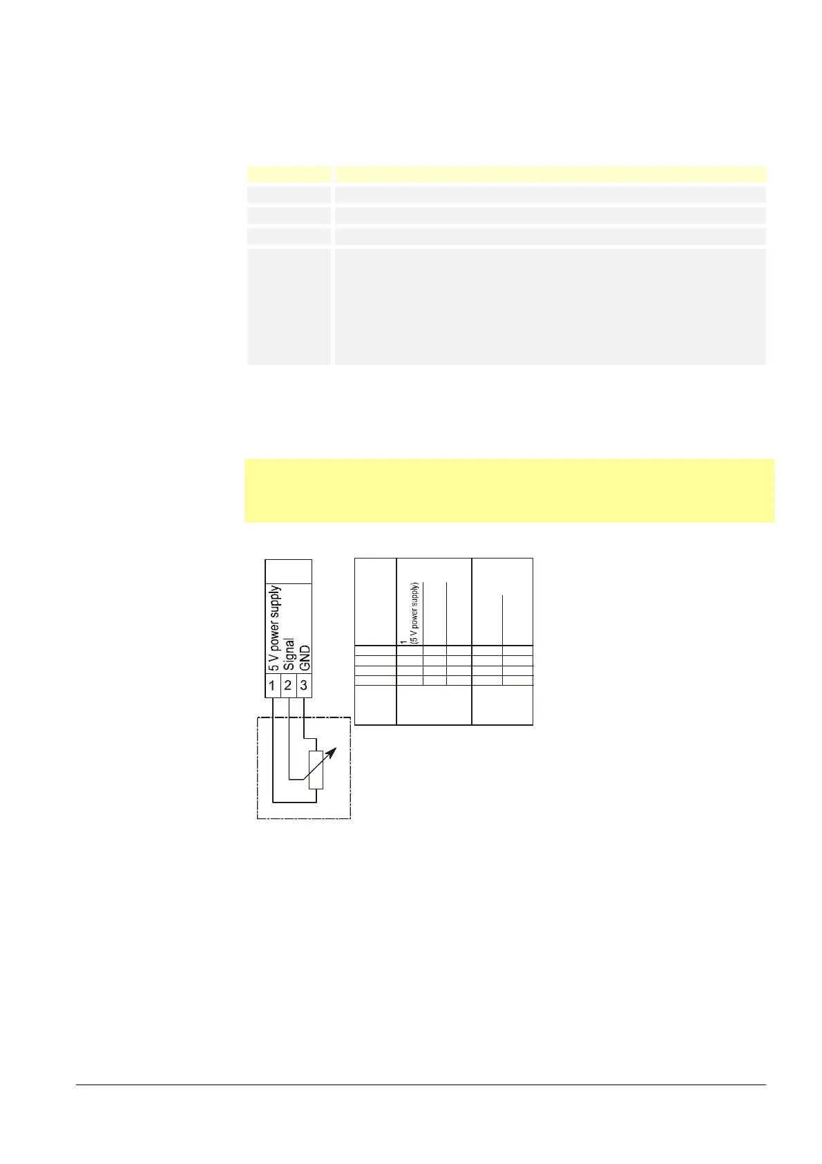
11.1.1 Connection diagram for feedback potentiometer
ASZ12.33
Note!
The connection diagram shown is merely an example which must be verified in the
individual case depending on the application!
PME7
X66
ASZ12.33
Ter m in a l X66
on the LME7...
Type
SQNx1...
SQMx1...
SQNx0...
SQMx0...
2
(Signal)
3
(GND)
a
b
c
a
b
c
a
b
c
a
b
c
Terminal potentiometer
(1 kOhm conductive
plastik 90°) ASZxx30
Rotation
direction
Clockwise
Counter-
clockwise
X
X
X
X
---
---
---
---
ab
c
7105d39e/1009
Figure 16: Connection diagram for feedback potentiometer ASZ12.33
 Loading...