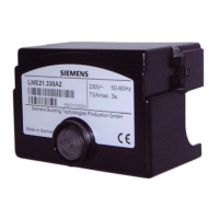
Do you have a question about the Siemens LME71.000A1 and is the answer not in the manual?
Provides critical warnings for safe operation and to prevent damage to equipment.
Details essential instructions for the correct physical installation of the unit.
Covers critical aspects of wiring, grounding, and cable management during installation.
Outlines essential checks and procedures to be performed before system startup.
Provides essential technical specifications for the LME7... basic unit, including voltage and weight.
Details the terminal ratings and input specifications for various signals and voltage detection.
Specifies the terminal ratings and output capabilities for different relays and circuits.
Explains the principles and parameters related to flame supervision using ionization probes and detectors.
Lists the necessary conditions that must be met before initiating a burner startup sequence.
Describes the unit's behavior and safety shutdown related to undervoltage conditions.
Details the sequence of actions the control takes when a fault occurs, leading to deactivation.
Provides instructions on how to reset the burner control after a lockout situation.
Details the meaning of the multicolor signal lamp indications for various operating states.
Explains how to activate and interpret diagnostic information for identifying fault causes.
Illustrates the program sequence for PME71.401 for fuel train connection diagrams.
Details the time table and parameter settings for the PME71.401 program sequence.
Illustrates the program sequence for PME71.402 for fuel train connection diagrams.
Details the time table and parameter settings for the PME71.402 program sequence.
Illustrates the program sequence for PME71.901 for fuel train connection diagrams, with and without valve proving.
Details the time table and parameter settings for the PME71.901 program sequence.
Illustrates the program sequence for PME72.521 for fuel train connection diagrams.
Details the time table and parameter settings for the PME72.521 program sequence.
Illustrates the program sequence for PME72.541 for fuel train connection diagrams.
Illustrates the program sequence for PME73.810 for fuel train connection diagrams, with and without valve proving.
Illustrates the program sequence for PME73.820 for fuel train connection diagrams.
Illustrates the program sequence for PME73.830 for fuel train connection diagrams.
Illustrates the program sequence for PME73.831 for fuel train connection diagrams.
Illustrates the program sequence for PME73.840 for fuel train connection diagrams.
Provides example connection diagrams for fuel train applications, including gas ignition types and valve proving.
Guides on setting the minimum power control step to prevent actuator hunting.
Provides a step-by-step guide for entering the OEM or heating engineer password.
Details the procedure for backing up settings and parameters to the program module.
Explains the process of restoring settings and parameters from the program module.
Explains how to display errors and fault messages when the unit is in lockout.
Details parameters related to PWM control, including ramp times and tolerance bands.
Describes PWM safety parameters for defining safe operation under various conditions.
Guides on making initial settings for basic PWM parameters on the OEM level.
Details the final settings for PWM safety parameters, including test modes.
Explains how to match fan speeds (P0, P1, P2) to application requirements.
| Brand | Siemens |
|---|---|
| Model | LME71.000A1 |
| Category | Controller |
| Language | English |


 Loading...