EasyManua.ls Logo

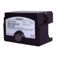
Siemens LME75

Siemens LME75
140 pages
To Next Page IconTo Next Page
Loading...
L M E 7…
Burner Controls
Combustion Controls
SCC Inc.
www.scccombustion.com
Technical Instructions LME-1000
June 11, 2019

Table of Contents

Question and Answer IconNeed help?

Do you have a question about the Siemens LME75 and is the answer not in the manual?

Siemens LME75 Specifications

General IconGeneral
Frequency50/60 Hz
Housing MaterialPlastic
TypeBurner control unit
ApplicationIndustrial burners
Supply Voltage230 V AC
Flame DetectionUV or ionization flame detection
StandardsEN 298
InputAnalog and digital signals
Power Supply230 V AC
Operating Temperature-20…+60 °C

Summary

Additional Flame Scanner Accessories - Optional

ACS410 Software for Laptop

Overview of the ACS410 software for parameter backups, startup reports, and trending.

ACS410 Cables

Details on the interface modules and cables required to connect the LME7 to a PC.

Important Safety Notes

LME71 Wiring Diagrams

PME71.111 A1 - Pilot or Direct Spark Wiring

Wiring diagram for LME71 with PME71.111A1: pilot/direct spark, purge, no actuator control, no valve proving.

PME71.112 A1 - Pilot or Direct Spark Wiring

Wiring diagram for LME71 with PME71.112A1: pilot/direct spark, no purge, no actuator, no valve proving.

PME71.901 A1 - PWM Blower Control Wiring

Wiring diagram for LME71 with PME71.901A1: PWM blower, direct spark, valve proving, no actuator control.

LME71 Parameter List

LME71 Phase Diagrams

PME71.111 A1 Phase Diagram

PME71.112 A1 Phase Diagram

PME71.901 A1 Phase Diagram

LME73 Wiring Diagrams

PME73.811 A1 - Modulating Actuator Wiring

Wiring diagram for LME73 with PME73.811A1: modulating actuator, valve proving, low fire ignition.

PME73.812 A1 - Modulating Actuator Wiring

Wiring diagram for LME73 with PME73.812A1: modulating actuator, independent ignition, no valve proving.

PME73.840 A1 - Actuator Control Wiring

Wiring diagram for LME73 with PME73.840A1: actuator control, valve proving, actuator disabled, low fire ignition.

LME73 Parameter List

LME73 Phase Diagrams

PME73.811 A1 Phase Diagram

PME73.812 A1 Phase Diagram

PME73.840 A1 Phase Diagram

LME75 Wiring Diagrams

PME75.811 A1 - Modulating Actuator Wiring

Wiring diagram for LME75 with PME75.811A1: modulating actuator, valve proving, self-check scanner/flame rod, low fire ignition.

PME75.812 A1 - Modulating Actuator Wiring

Wiring diagram for LME75 with PME75.812A1: modulating actuator, independent ignition, no valve proving, self-check scanner/flame rod.

LME75 Parameter List

LME75 Phase Diagrams

PME75.811 A1 Phase Diagram

PME75.812 A1 Phase Diagram

Commissioning a New LME7 Burner Control

Parameter Backups Restores

Blower Speed Monitoring

Commissioning PWM Blower Application

Adjusting P0, P1, P2 via LME7 Display

Adjusting P0, P1, P2 via AZL23 Display

Troubleshooting Introduction

Navigating the Fault History

Resetting Faults

Methods for resetting faults on the LME7 burner control.

Complete Fault Code List

Other Common Faults

Modbus RTU and BACnet MSTP Communication

Modbus RTU Connection Details

BACnet MSTP Connection Details

Using the OCI417 Configuration Utility

Modbus Mapping

BACnet Mapping

ACS410 Software Introduction

Software Installation

Connecting to a PC

Saving a Parameter Set to a PC

Uploading a Parameter Set to an LME7

Creating an LME7 Startup Report

Synchronizing LME7 and PME Parameters

Saving and Viewing Trends

Viewing the Status Screen

Honeywell Modutrol IV Motor with LME75

Two Flame Detectors

Procedure and wiring diagrams for using two flame detectors with LME7 burner controls.

PME75.811 A1 Phase Diagram with Relays

Appendix A: Two Flame Detectors

Two Flame Detectors

Related product manuals