EasyManua.ls Logo

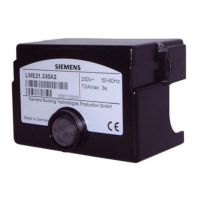
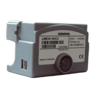
Siemens LME22.331A2 User Manual

Siemens LME22.331A2
25 pages
To Next Page IconTo Next Page
Page #1 background imageLoading...
Page #1 background image
CC1N7101en
27.11.2008
Building Technologies
HVAC Products
7
101
Burner Controls LME...
Burner controls for the supervision of 1- or 2-stage gas or gas / oil burners of
small to medium capacity, operation, with or without fan in intermittent.
The LME… and this Data Sheet are intended for use by OEMs which integrate the
burner controls in their products.
Use, features
LME… burner controls are used for the startup and supervision of 1- or 2-stage gas or
gas / oil burners in intermittent operation. The flame is supervised by an ionization
probe or flame detector QRA… with ancillary unit AGQ3…A27 for gas / oil forced draft
burners or blue–burning flames with blue-flame detectors QRC...
In terms of housing dimensions, the LME... are identical with the LGB… and LMG…
burner controls (refer to «Type summary»).
- For gas burners with or without fan to EN 298: 2003
- For gas burners with fans conforming to EN 676
- For oil burners to EN 230: 2005
- Undervoltage detection
- Air pressure supervision with functional check of the air pressure switch during
startup and operation
- Electrical remote reset facility
- Multicolor indication of fault status and operational status messages
- Limitation of the number of repetitions
- Accurate control sequence thanks to digital signal handling
- Controlled intermittent operation after 24 hours of continuous operation
Supplementary documentation
Product Range Overview LME…............................................................................ Q7101
Use
Features
Question and Answer IconNeed help?

Do you have a question about the Siemens LME22.331A2 and is the answer not in the manual?

Siemens LME22.331A2 Specifications

General IconGeneral
Frequency50/60 Hz
Protection classIP 20
TypeLME
Product typeBurner controller
ApplicationIndustrial burners
Flame detectionUV and IR flame detectors
VoltageAC 230 V
Input voltageAC 230 V
Operating temperature-20...+60 °C

Summary

Burner Controls Overview

Use of LME Burner Controls

Describes the application of LME burner controls for startup and supervision of gas/oil burners in intermittent operation.

Important Safety and Operational Notes

General Safety Warnings

Crucial safety instructions to prevent injury and damage, emphasizing qualified personnel and electrical safety.

Installation and Wiring Procedures

Installation Notes for Burner Controls

Guidelines for cable routing, conductor separation, fuse installation, and earthing for safe and reliable burner control setup.

Commissioning Safety Checks

Safety Checks for Commissioning

Procedures for verifying burner startup, simulated flame loss, and air pressure failure to ensure safe operation.

Technical Data: General and Environmental

General Unit Specifications

Provides key technical details like mains voltage, frequency, power consumption, weight, and safety class.

Technical Data: UV Flame Supervision

Technical Data: Other Supervision and Functions

Preconditions for Burner Startup

Lists requirements for burner startup, including reset, closed contacts, and no undervoltage.

Fault Handling and Control Reset

Fault Causes and Responses

Details responses to faults like mains failure, undervoltage, loss of flame, and external faults.

Resetting the Burner Control

Instructions on how to reset the burner control after a lockout using the lockout reset button.

Operation and Diagnostics Interface

Lockout Reset Button and Multicolor LED

Identifies the lockout reset button (EK) and multicolor LED for operation and diagnostics.

Detailed Diagnostics and Error Codes

Activating Diagnostics Procedures

Explains how to activate visual diagnostics (cause of fault) and interface diagnostics using the lockout reset button.

Error Code Table for Fault Diagnosis

Lists specific blink codes of the signal lamp (LED) and their corresponding possible causes of fault.

Connection Diagram: LME11 Series

Connection Diagram: LME21 Series

Application Examples: Actuator Control

Connection Diagram: LME22/LME23 Series

Application Examples: Modulating Burners

Connection Diagram: LME41 Series

Connection Diagram: LME44 Series

Wiring Diagram and Control Sequence

Presents the electrical connections and timing sequence for the LME44 burner control.

Related product manuals