Do you have a question about the Siemens LME39 Series and is the answer not in the manual?
Details on the application and key features of the LME39... gas burner controls for 1- or 2-stage burners.
References to related product range overview and basic documentation for LME39 series.
Essential safety instructions for handling, installation, and service work on the unit, including electric shock hazards.
Notes on actuator integration, actuator timing, and compliance with national safety regulations during mounting.
Details on how burner control characteristics are set and the responsibility for parameter changes.
Guidelines for marking the unit with OEM settings and parameters as per EN 298 standards.
Guidance on cable routing, conductor connections, and compliance with electrical safety standards.
Illustrations and explanations for correct wiring of components, including neutral conductors for safety.
Best practices for signal transmission and connection of flame detectors for reliable operation.
Mandatory safety checks before plant commissioning, including flame detection and air pressure.
Instructions regarding the disposal of electrical and electronic components according to local legislation.
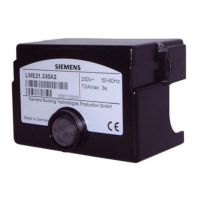
Description of the unit's housing, internal components, and interface connections.
Overview of visual indicators, diagnostic outputs, and fault status messages.
Details on communication interfaces like AZL2, OCI410, and ACS410 PC software.
List of key programmable time parameters affecting burner startup and operation.
Electrical and physical specifications of the LME39... burner control, including voltage, power, and weight.
Permissible cable lengths for various connections and current carrying capacity of terminals.
Specifications for climatic, mechanical, and humidity conditions during storage, transport, and operation.
Designed lifetime of the burner control based on startup cycles and operational years.
Principles of flame supervision using ionization probes, including detector voltage and current requirements.
Diagram and explanation of the circuit used for measuring ionization probe signals.
Technical data for UV detectors (QRA...) and ancillary units (AGQ3...A27) used with the burner control.
Technical specifications and connection requirements for the AGQ3...A27 ancillary unit.
Technical diagrams illustrating the measurement circuits for UV detector current.
Conditions required for the burner control to initiate a startup sequence.
Behavior of the burner control during undervoltage conditions and controlled intermittent operation.
Sequence of operations and responses when faults like mains failure or no flame occur.
Procedures for resetting the burner control after lockout and parameters for limiting startup repetitions.
Overview of the ACS410 PC software for visualization, parameterization, and resetting of the unit.
Explanation of the multicolor signal lamp (LED) and color codes for operational status.
How to interpret visual diagnostics and the color code table for the LED during various states.
Methods for diagnosing fault causes using LED blink codes and the error code table.
Diagrams illustrating the control sequence and wiring for LME39.100 series.
Diagrams illustrating the control sequence and wiring for LME39.400 series.
Examples of connection diagrams, emphasizing the need for adaptation to specific applications.
Detailed dimensions of the LME39... burner control unit and its plug-in base.
Dimensions for the AGQ3...A27 ancillary unit and its available models.
| Frequency | 50/60 Hz |
|---|---|
| Protection Class | IP40 |
| Mounting | Base mounting |
| Standards | EN 298 |
| Application | Oil and gas burner management |
| Flame Supervision | Ionization or UV flame detector |
| Output Signal | Relay |
| Operating Temperature | -20 to +60 °C |


