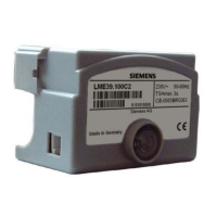
Do you have a question about the Siemens LME39.100C2 and is the answer not in the manual?
General warnings about unit operation, safety, and electrical hazards.
Notes on using actuators and communication interfaces.
Requirements for complying with national safety regulations during mounting.
Guidance on routing cables, wiring, earthing, and component connections.
Details on using the RJ11 interface for BCI communication.
Best practices for signal transmission and connecting flame detectors.
Crucial safety checks and points to verify before plant commissioning.
Lists applied directives, standards, and conformity marks.
Designed lifetime of burner controls and replacement recommendations.
Guidelines for disposing of electronic components according to legislation.
Application of LME39... for gas burners and supervision.
Key features and capabilities of the LME39... burner control.
Description of the LME39... housing, components, and connectivity.
Information on safety-related time parameters and their adjustment.
How the unit indicates status and faults, and diagnostic methods.
Methods for operating and parameterizing the unit via AZL2 or ACS410.
Overview of product variants and their technical time parameters.
Lists plug-in bases and cable holders for connecting the unit.
Describes optical interfaces, BCI modules, and PC software for service.
Details on various display and operating units (AZL21, AZL23).
Information on UV flame detectors (QRA series) and ionization probes.
Lists different types of actuators (SQN series) with their data sheets.
Lists other accessories like valve proving systems, RC units, PTC resistors, and ancillary units.
Electrical specifications, mounting, degree of protection, and terminal ratings.
Specifications for the AGV50 signal cable used for display connection.
Climatic, mechanical, and operational conditions for storage, transport, and use.
Technical data and operating principles for ionization flame supervision.
Diagram and components for the ionization probe measuring circuit.
Technical data for UV flame supervision using AGQ3 and QRA detectors.
Conditions that must be met before a burner can start.
How undervoltage affects operation and safety shutdown.
Automatic shutdown and restart after 24 hours of continuous operation.
Describes responses to various fault conditions and lockout codes.
Procedures for resetting the unit after a fault or lockout.
How repetitions of startup attempts are handled and limited.
Role and basic tasks of the ACS410 PC software for burner controls.
Overview of operation, lockout reset button, and diagnostics choices.
How the unit indicates status via multicolor signal lamp (LED).
Steps to activate visual and interface diagnostics to identify faults.
Detailed program sequence showing phase numbers, parameters, and terminal states.
Internal wiring diagram showing connections and logic.
Wiring diagrams for common applications with actuators.
Specific application example using the LDU11 system.
Program sequence for LME39.400, showing phases and terminal states.
Internal wiring diagram for LME39.400.
Wiring example for burners with fan control via auxiliary contactor.
Explains symbols and abbreviations used in diagrams and text.
Mechanical dimensions of the LME39... unit in mm.
Dimensions of the unit with AGK20 extension.
Mechanical dimensions of the AGQ3.xA27 ancillary unit.
Details on the AZL2 unit's display, buttons, and their functions.
Explains the various symbols shown on the AZL2 unit's display.
Procedure for manually initiating a lockout via the unit.
Standard display modes including standby and startup/shutdown phases.
How the unit is displayed when in standby mode.
Shows program phases and controlled components during startup/shutdown.
Table detailing the meaning of each program phase (Ph1, Ph2, etc.).
How the display shows operation stages (oP: P1, oP: P2).
Shows how faults and lockout status are displayed.
Procedures for resetting the unit after errors or faults.
Diagram showing how to navigate between Standby, Info, Service, Operating, and Parameter levels.
How to access and navigate the Info level display.
How to display the program sequence creation date.
How to display the identification number.
How to display the burner ID.
How to view and reset the resettable startup count.
How to display the total number of startups.
How to exit the Info level and return to operating mode.
How to access and navigate the Service level.
How to view error history entries.
How to view error history entries.
How to display the mains voltage.
How to display the flame intensity reading.
How to exit the Service level.
Accessing and changing parameters, OEM settings. Caution and Warning notes.
Step-by-step guide for entering OEM and heating engineer passwords.
Procedure to change the heating engineer's password.
Procedure to change the OEM's password.
How to view and edit preignition time (parameter 226).
How to view and edit preignition time (parameter 226).
How to view and edit air pressure time (parameter 224).
How to view and edit air pressure time (parameter 224).
How to view actual errors and diagnostic codes (parameter 701).
How to view actual errors and diagnostic codes (parameter 701).
Table listing error codes, clear text, and potential causes.
Comprehensive list of parameters for LME39.100, their numbers, ranges, and settings.
Comprehensive list of parameters for LME39.400, their numbers, ranges, and settings.
| Brand | Siemens |
|---|---|
| Model | LME39.100C2 |
| Category | Controller |
| Language | English |


