34/73
Building Technologies Division Basic Documentation LME39… CC1P7106en
10 Inputs and outputs/internal connection diagram/program sequence of LME39.100... 08.12.2017
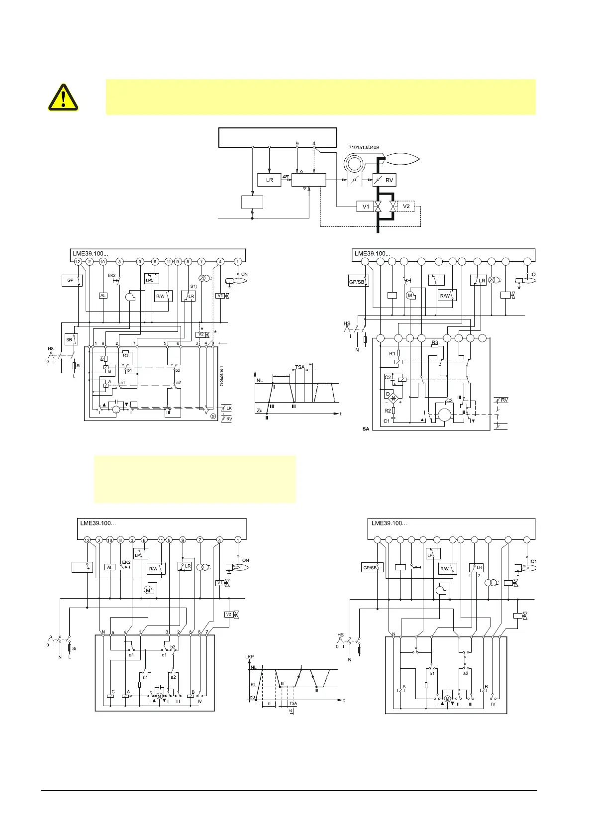
10.3 Application examples
Attention!
The connection diagrams shown are merely examples which must be adapted in the
individual case depending on the application!
Control of actuators of 2-stage or 2-stage
modulating burners. Controlled prepurging
with high-fire air volume.
For information about actuators:
SQN3... see Data Sheet N7808
SQN7... see Data Sheet N7804
SQN9... see Data Sheet N7806
5
SA
L
SB/R/W
12
12
2
10
83
6
11
9
57
4
1
AL
EK2
LP
V1
0
L
68102
13
7
9
LK
K2
K1
MS
KL
LKP
t1
t4
N
M
N
M
1)
2)
Si
SQN3...151... or SQN3...251...
SQN90.220.../2-stage modulating
control
* Note:
With 2-stage modulating burners (with gas regulation
damper), fuel valve 2 and the dotted connection
between terminals (*) are not required.
IVIV
HS
GP/SB
Z
7106a09/1011
4
1
5
L
a1
12
AL
EK2
3
8
3
2
6
8 7
b2
Z
V1
4
1
10
9
5
7
V2
2
6
11
M
Si
SQN7...454/2-stage control
1 wire control
SQN7...424/2-stage control
2 wire control
Figure 12: Application examples LME39.100...
 Loading...