24/73
Building Technologies Division Basic Documentation LME39… CC1P7106en
6 Technical data 08.12.2017
6.4 Flame supervision with ionization probe
At mains voltage
UN = AC 120 V ¹) UN = AC 230 V ¹)
Detector voltage between ionization probe and ground
(AC voltmeter Ri 10 M)
AC 50...120 V AC 115...230 V
Switching threshold (limit values):
Switching on (flame on) (DC ammeter Ri 5 k)
Switching off (flame off) (DC ammeter Ri 5 k)
DC 1.5 µA
DC 0.5 µA
DC 1.5 µA
DC 0.5 µA
Detector current required for reliable operation
DC 3 µA DC 3 µA
Switching threshold in the event of poor flame during operation
(LED flashes green)
Approx. DC 5 µA Approx. DC 5 µA
Short-circuit current between ionization probe and ground
(AC ammeter Ri 5 k)
AC 50...150 µA AC 100...300 µA
Table 3: Data ionization probe
¹) For applications outside the European Union, operation at mains voltage AC 120 V/AC 230 V ±10% is
ensured
Flame supervision with ionization is accomplished by making use of the conductivity and
rectifying effect of the flame.
The DC current that flows in the presence of a flame (ionization current) is largely
proportional to the flame quality. This current is measured in the flame signal amplifier.
The amplifier is designed such that it only responds to the DC current component of the
flame signal. This ensures that a short circuit between the ionization probe and ground
cannot simulate a flame signal (since in that case AC current would flow).
Note!
The ignition (ignition spark) can have a negative effect on the ionization current
formation during startup.
To minimize the impact
the positioning of the ionization probe must be checked and optimized
it may be beneficial to replace the electrical connections (phase / neutral) on the
primary side of the ignition transformer
A short-circuit between ionization probe and ground initiates a non-alterable lockout.
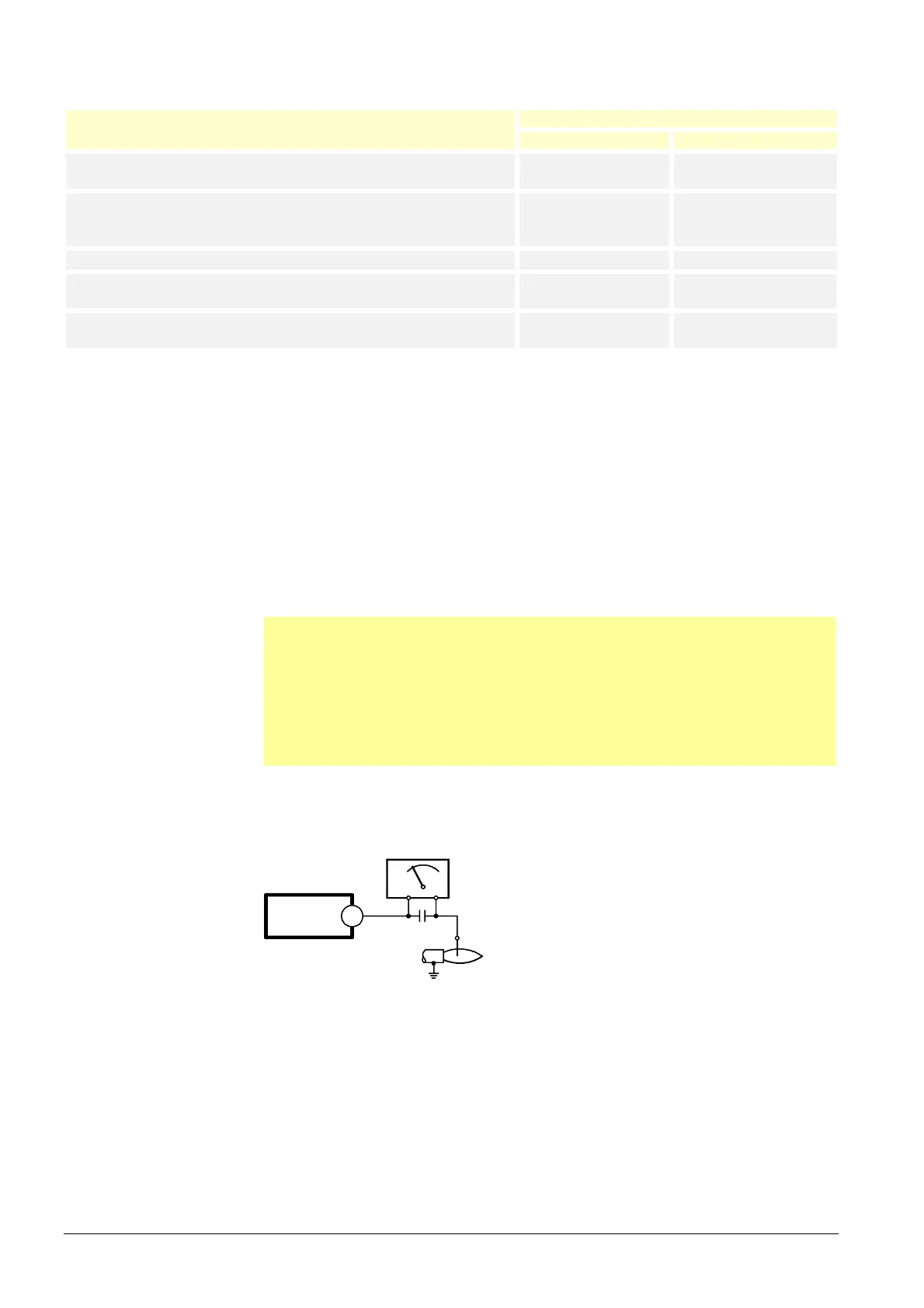
6.4.1 Measuring circuit
LME39...
1
7106v01/0405
M
C
+
+
-
ION
Legend
C Electrolytic capacitor 100...470 µF; DC 10...25 V
ION Ionization probe
M Microammeter, Ri max. 5,000
Figure 6: Measuring circuit: Ionization probe
For detector currents, see General unit data.
 Loading...