38/116
Smart Infrastructure Basic Documentation LME7... CC1P7105enr
4 Technical data 24.07.2020
4.12.2 QRA2 / QRA4 / QRA10 (LME71 / LME73 only)
Caution!
If QRA2-UV tubes, QRA4-UV tubes, or QRA10-UV tubes are used for flame
supervision on the LME7, it must be ensured that the burner control is
permanently connected to power (EN 298), thus enabling the system to detect
detector failures during startup and shutdown. The system generally operates
with QRA flame detectors in intermittent operation. Failure to observe this
information poses a risk of the safety functions being impaired.
For Technical data, refer to Data Sheet N7712, UV flame detector QRA2 /
QRA10!
For Technical Data, refer to Data Sheet N7711, UV flame detector QRA4!
Threshold values when flame is supervised by QRA
- Start prevention (extraneous light) Intensity (parameter 954) approx. 12%
- Operation Intensity (parameter 954) approx. 13%
Operating voltage AC 280 V ±15%
Mains frequency
50...60 Hz 6%
Required detector current Min. 70 µA
Possible detector current during operation
Max. 700 µA
Perm. length of detector cable
(normal cable, laid separately) ¹)
Max. 100 m, unshielded
¹) Multicore cable not permitted
Parameters Function
954 Flame intensity
L
...
7105z14/0119
QRA -
X10-06
1
2
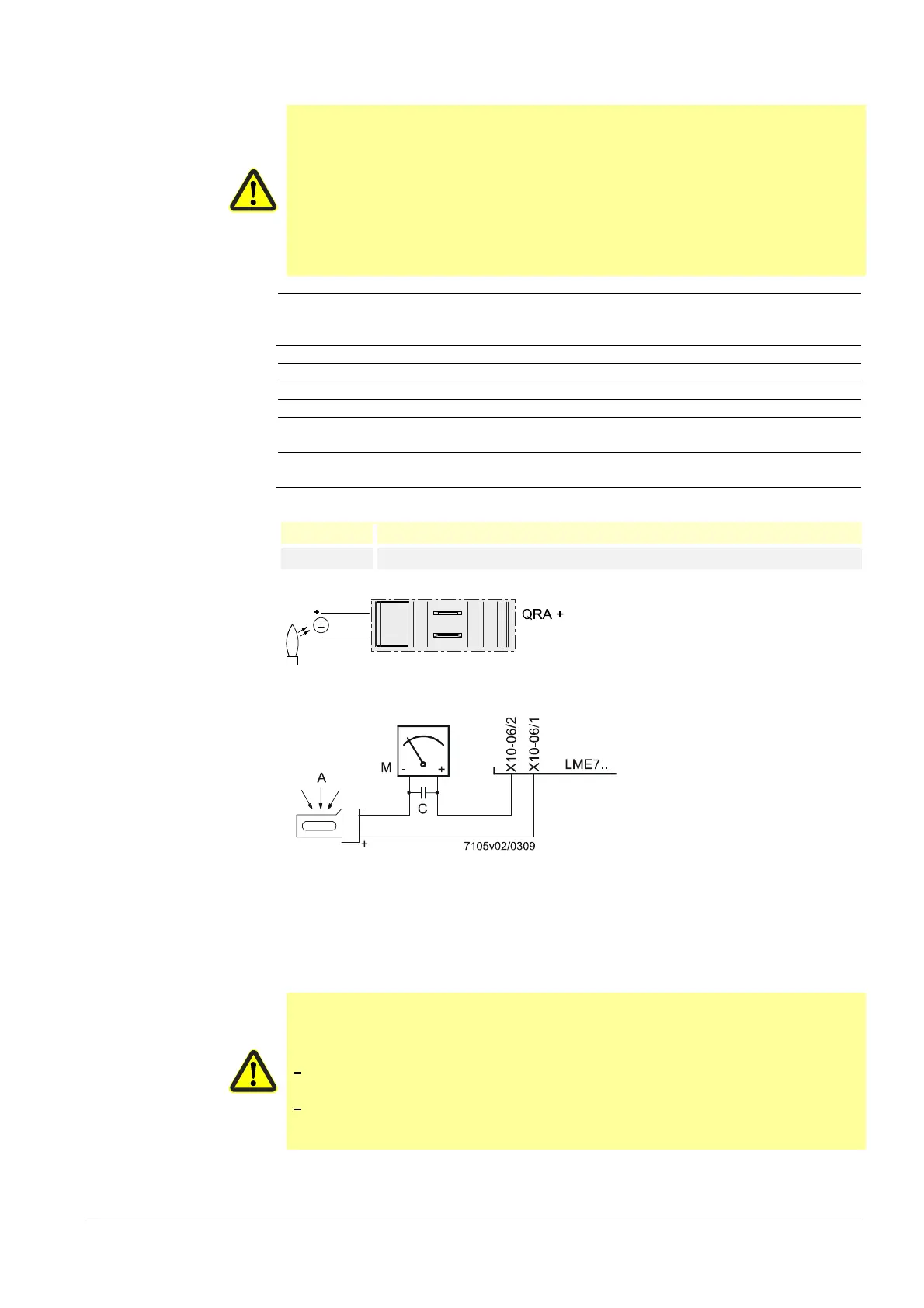
Flame detector QRA
QRA...
Figure 5: Measuring circuit for QRA
Legend
A Exposure to light
C Electrolytic condenser 100...470 µF; DC 10...25 V
M
Microammeter Ri max. 5,000
Warning!
Input QRA is not short-circuit-proof!
Short-circuits of terminal X10-06 pin 2 against earth can destroy the QRA
input
Simultaneous operation of flame detector QRA and ionization probe is not
permitted. If not observed, there is a risk of impairment of safety functions.
To ensure that the age of the UV tubes can be determined, the LME7 must
always be connected to mains voltage. Failure to observe this information
poses a risk of the safety functions being impaired
Connection diagram
Measuring circuit for detector
current measurement
 Loading...