36/116
Smart Infrastructure Basic Documentation LME7... CC1P7105enr
4 Technical data 24.07.2020
4.12 Flame supervision
4.12.1 Ionization probe
No-load voltage at terminal ionization
probe (terminal X10–05 pin 2)
AC 300 V
Warning!
The ionization probe must be protected against electric shock hazard!
When monitoring ionization currents in earth-free mains, connect terminal
X10-05 pin 1 to burner ground
Short-circuit current Max. AC 1 mA
Required detector current Min. DC 1 µA, display approx. 20%
Possible detector current Max. DC 40 µA, display approx. 100%
Perm. length of detector cable
(normal cable, laid separately) ¹)
30 m (100 pF/m), unshielded
¹) Multicore cable not permitted
Note:
As the detector line capacitance (line length) increases, the voltage at the ionization
probe und thus the detector current will drop. Extremely long line lengths and very
high-ohmic flames might necessitate the use of low-capacitance cable (e.g. ignition
cable). In spite of special electronic circuits designed to compensate possible adverse
effects of the ignition spark on the ionization current, it must be made certain that the
minimum detector current required is already available during the ignition phase. If
this is not the case, the primary ignition transformer connections must be
interchanged and/or the electrodes relocated.
Threshold values when flame is supervised by ionization
- Start prevention (extraneous light) Intensity (parameter 954) approx. 12%
- Operation Intensity (parameter 954) approx. 13%
Parameters Function
954 Flame intensity
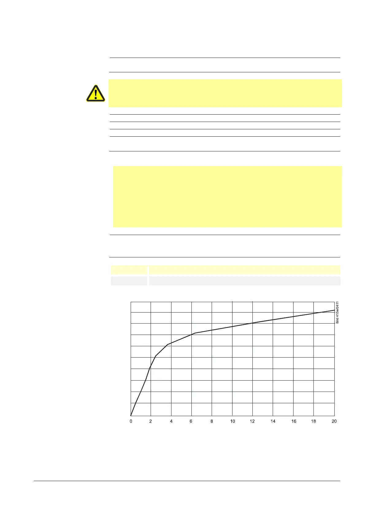
ION input
Ionization current in µA
lame intensit
in %
100
90
80
70
60
50
40
30
20
10
0
Figure 3: Ionization input at AC 120 V / AC 230 V
 Loading...