44 ซ.บรมราชชนนี 70 ถ.บรมราชชนนี ศาลาธรรมสพน์ ทวีวัฒนา กทม. 10170.
website: https://www.add-furnace.com/ โทร: 02-888-3472
Line ID: @add11 Wechat ID: add0883001122
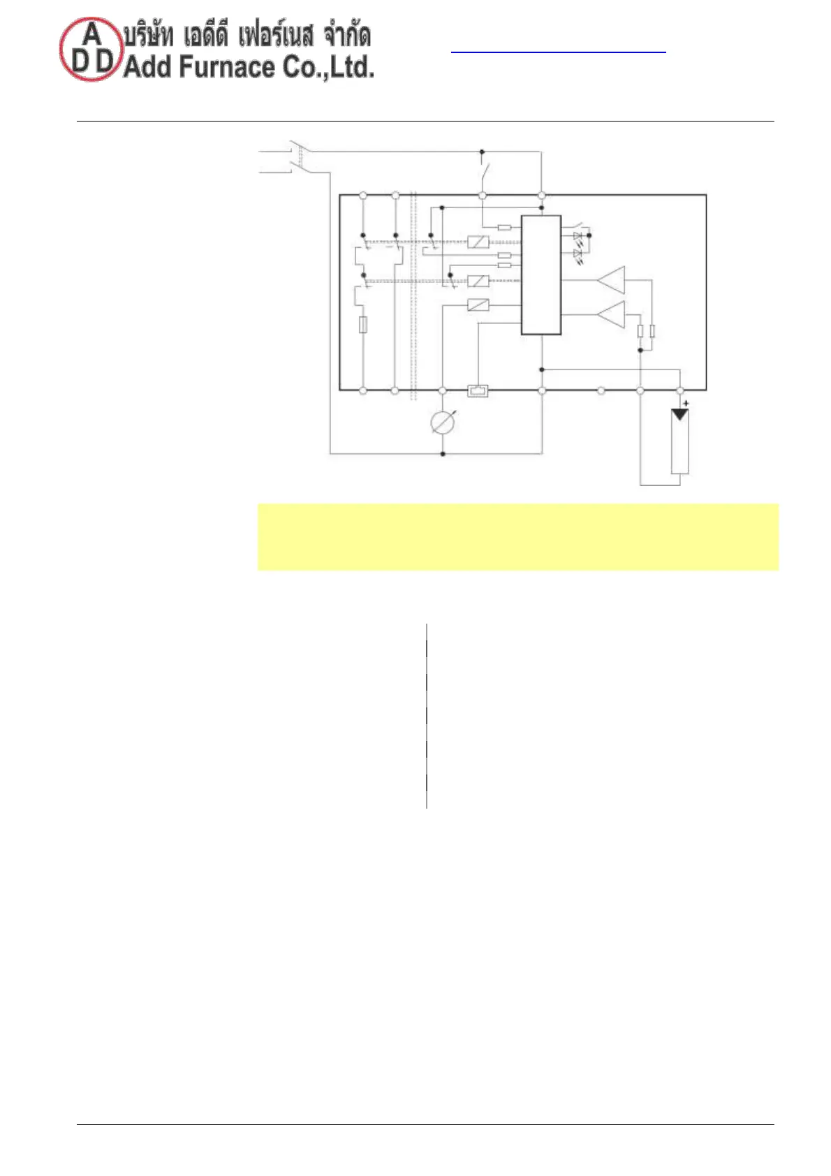
Connection diagram and internal diagram
LFS1.1 with RAR9
HS
L
EK
LFS1.1...
FR
fr1 fr2
HR LED
hr1
Si
Note!
Β The test mode switchover (T/B) is only required in conjunction with the control
unit LEC1. Otherwise terminal 6 of the LFS1 must be connected directly to the
phase conductor «L» at terminal 1 in this case.
Key
(Burner Communication Interface)
Lockout reset button (internal)
Internal LED (three-colored)
Flame signal amplifier test mode switchover
(QRA, RAR9: Only required in case of replacement by
Internal auxiliary relay (test mode switchover)
Auxiliary relay NO contact
Voltage output for outputting flame signal strength
23/40
Building Technologies CC1N7782en 18.04.2018
 Loading...