The following instructions are for the installation of Siemens Sentron HCP switches in
a deep type panelboard (P5) as a Main.
The parts provided in this kit are for
connection to a 3 phase / 4 wire system.
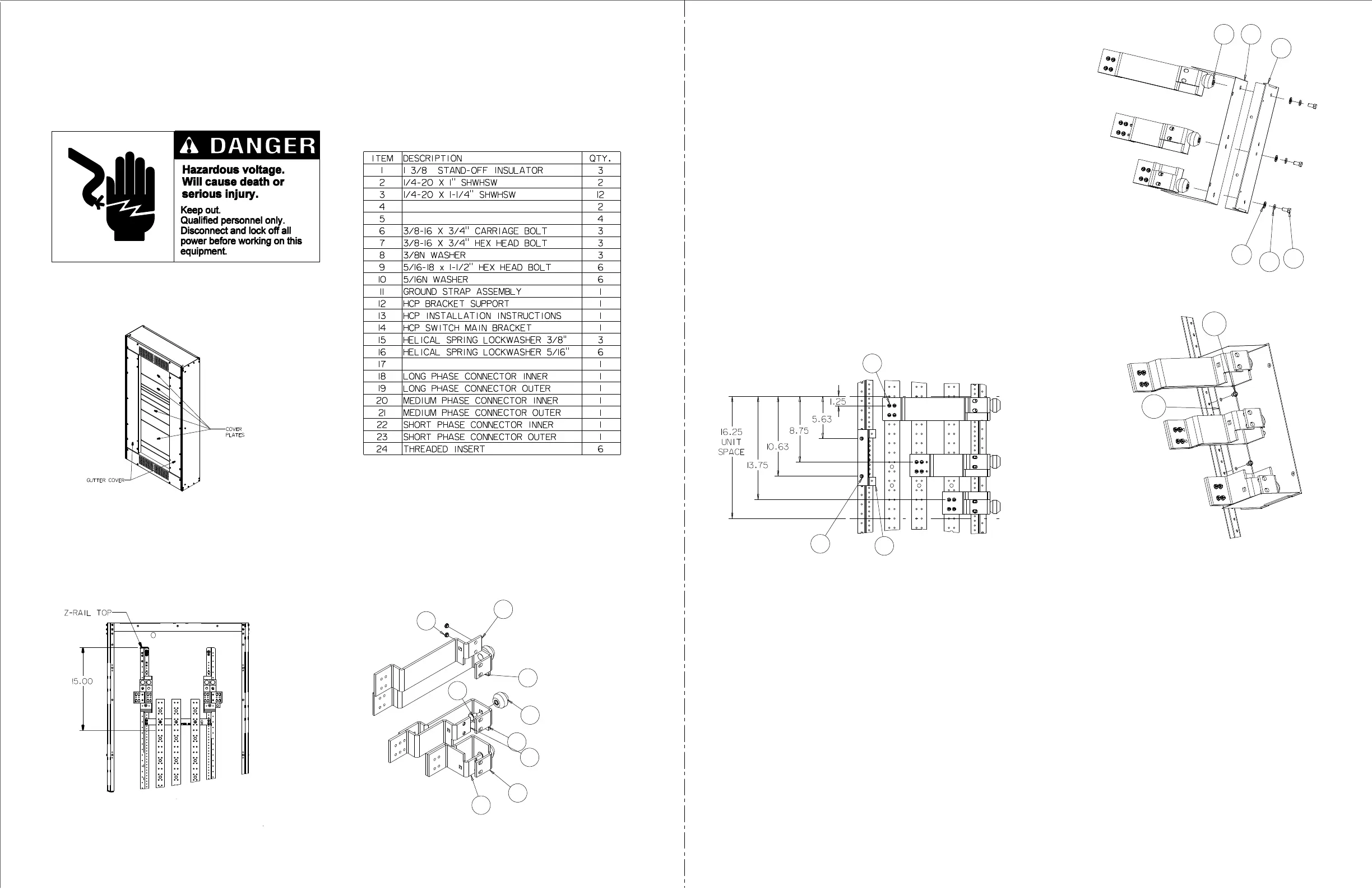
Reference fig. 2 - To locate mounting position
of a HCP main switch, measure 15” from the top
(or bottom for bottom feed applications) of Z-rail and
mark position on Z-rail. The marked position acts as
top (or bottom) of unit space for the strap assembly
as shown in fig. 4.
Open the shipping box and check the contents against
the following list:
Figure 2
-2-
3.
Figure 1
Installation Instructions
4.
-3-
11-D-1023-01 RE
V. 0
5.
Reference fig. 3 - Installing inserts and stand-off insulators. Insert
two threaded inserts (item 24) into the two 0.406” holes on the long
phase connector inner (item 18) oriented as shown. (This is
accomplished by tapping the inserts into the under-side of the
connector with a hammer.) Do not strike hard enough to damage
the threads. Repeat steps for medium (item 20) and short (item 22)
phase connectors. Insert 3/8-16 X 3/4” carriage bolt (item 6)
through the 0.437” square opening in the long phase connector
outer (item 19) into the 1-3/8 stand-off insulator (item 1)
and tighten. Repeat steps for medium (item 21) and short
(item 23) phase connectors.
Figure 3
6.
Reference fig. 4 -
Attach phase straps and breaker support.
Locate the 0.228” diameter hole on the section bus 1.25” down
from the top of the unit space established in step 3. Insert
1/4-20 X 1-1/4” screw (item 3) through the 0.312” diameter
hole in the long phase connector inner (item 18), through the
0.312” diameter hole in the long phase connector outer (item 19)
into the section bus. Hand tighten. Repeat for remaining three
openings in long phase connectors. Locate the 0.228” diameter
hole on the section bus 8.75” down from the top of the unit space.
Insert 1/4-20 X 1-1/4” screw (item 3) through the 0.312” diameter
hole in the medium phase connector inner (item 20), through the
0.312” diameter hole in the medium phase connector outer (item 21)
into the section bus. Hand tighten. Repeat for remaining three openings
in medium phase connectors. Locate the 0.228” diameter
hole on the section bus 13.75” down from the top of the unit space.
Insert 1/4-20 X 1-1/4” screw (item 3) through the 0.312” diameter
hole in the short phase connector inner (item 22), through the
0.312” diameter hole in the short phase connector outer (item 23)
into the section bus. Hand tighten. Repeat for remaining three openings
in short phase connectors.
Align the outside edge of the three phase
connectors.
Tighten and torque screws (item 3) to values shown on rear
of dead front.
Locate the 0.228” diameter hole on the Z-rail 5.625” down from
the top of the unit space. Insert 1/4-20 X 7/16” screw through the 0.312”
hole in the HC
P bracket support (item 12) into the 0.228” hole. Insert
the second 1/4-20 X 7/16” (item 5) screw and tighten.
Figure 4
7.
Reference fig. 5, and fig. 6 - Installing support barrier assembl
y.
Position the barrier (item 17) between the HC
P bracket support
(item 14) and the stand o
ff insulators (item 1). Using the 3/8-16
hex head bolts (item 7), the 3/8” lock washers (item 15) and the 3/8”
flat washers (item 8) attach insulation and support barrier to the
stand o
ff insulators.
Insert two 1/4-20 X 7/16” screws (item 5) through the HC
P
bracket (item 14) into the 0.228” diameter holes in the Z-rail.
Tighten screws and bolts.
Figure 6
22
23
20
21
1
19
6
18
24
3
Note: orientation shown for left feed. For right
feed, rotate 180 degrees.
1
14
5
Figure 5
5
12
17
14
8
15
7
Lock off power supplying this equipment before working
on it.
Reference fig. 1 - Remove the (2) gutter covers, deadfront
and all cover plates.
1.
2.
SUPPORT BARRIER
 Loading...