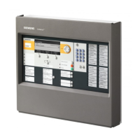
Do you have a question about the Siemens Cerberus PYROTRONICS MXL and is the answer not in the manual?
General information about the MXL Control Panel, its features, and capabilities.
Details on the MXL System's software, including its multitasking operating system and functionality.
Lists and describes the main components of the basic MXL Control Panel configuration.
Details on the MME-3 and MLE-6 enclosures, including their description and installation.
Instructions for installing the backbox, front door, and filter plates for MME-3/MLE-6 enclosures.
Procedure for installing the MPS-6 or MPS-12 power supplies and connecting them securely.
Explains how to use the Keyboard/Annunciator Panel (MKB) in local mode for system operation.
Describes the MXL display, its two lines of 40 characters, and how it shows system status.
Details the functions of the System Control Keypad and the System Control LEDs.
Explains how the MXL system handles alarms, including responding to alarms and acknowledging them.
Details how the MXL system announces alarms using the MKB LEDs, audible signals, and display.
Instructions on how to view the list of alarms on the MXL system.
Procedure for acknowledging individual alarms on the MXL system.
Instructions on how to block the acknowledgement of an alarm on the MXL system.
How to silence audible alarms and the system.
Explains how the MXL system announces and handles supervisory events.
Details how the MXL system announces supervisory events via LEDs and display.
Instructions for viewing the list of supervisory events on the MXL system.
Procedure for acknowledging individual supervisory events on the MXL system.
Explains how the MXL system announces and handles trouble conditions.
Details how the MXL system announces trouble conditions via LEDs and display.
Instructions for viewing the list of trouble events on the MXL system.
Procedure for acknowledging individual trouble events on the MXL system.
Explains how the MXL system announces and handles security conditions.
Details how the MXL system announces security conditions via LEDs and display.
Instructions for viewing the list of security conditions on the MXL system.
Procedure for acknowledging individual security conditions on the MXL system.
Details the procedures for performing hard resets and soft resets on the MXL system.
Explains how to use the MKB in global mode for system operation.
Description of the Block ACK function and its operation in global mode.
Explanation of the AUD SILENCE function and its operation.
Details the operation of various function keys on the MKB.
Explains the use of the numeric keypad on the MKB.
Overview of voice system operations, including paging, alerts, and tone generation.
Describes the four categories of sound: Page, Evac, Alert, and Other.
Lists the standard tones available for use in the MXL System.
Explains the meaning of the different colored LEDs on the MXL system.
How to program automatic voice operations for detecting conditions.
How to manually initiate Evac or Alert, or modify active conditions.
Details the different audible signals, their causes, and how to respond.
Explains how telephone call-ins work on the MXL system.
Details how to perform phone pages and warden's pages on the MXL system.
How to silence voice audibles on the MXL system.
Explains various utility functions available on the MXL system, like EXT SOURCE and CLEAR MANUAL.
Procedure for using the DENTY ACCESS function on the MXL system.
How to select external sources for audio on the MXL system.
Explains telephone operation on the MXL system.
Table detailing the usage of VSM switches for various operations.
Overview of voice system operations, including steps and types of operations.
Details on networked voice operations, including Networked OCC-1 and Networked ACM-1.
Table of VSM switch usages for networked systems.
Guide to navigating and using the MXL System menu for operation.
Instructions for entering the system password to access the menu.
General guidance on navigating the MXL System menu using the keypad and ENTER.
Explanation of how modules and devices are addressed and identified in the MXL System.
Details the four options within the Acknowledge menu: Alarm, Supervsy, Trouble, Security.
Procedure to acknowledge alarms on the MXL system.
Procedure to acknowledge supervisory events on the MXL system.
Procedure to acknowledge trouble events on the MXL system.
Procedure to acknowledge security conditions on the MXL system.
Details the eighteen items in the List Menu for viewing system information.
Shows all alarms currently in the system and how to view them.
Shows all supervisory events currently in the system and how to view them.
Shows all trouble events currently in the system and how to view them.
Shows all security conditions currently in the system and how to view them.
Instructions to view sensitivity settings of devices on analog loops.
Instructions to view device voltages on analog loops.
Instructions to view calibration data for XLD-1 devices.
Instructions to view ID information for XLD-1 devices.
Instructions to view the module type for a particular module.
Instructions to view the software version of the MXL system or modules.
Instructions to view the output states of individual devices in the MXL.
Instructions to view the uses of individual devices as programmed in the CSG-M.
Instructions to display the panel address of the panel.
Instructions to show settings in percent/ft for analog devices.
Instructions to display operational characteristics of ASD devices.
Instructions to display the alarm state of a disarmed device.
Overview of the Control Menu functions, including Reset System, Arm/Disarm, and Output control.
Procedure to reset the MXL System using the Control Menu.
Procedure to change sensitivity settings of smoke detectors using the Control Menu.
Procedure to arm or disarm an initiating device using the Control Menu.
Procedure to turn output devices on or off using the Control Menu.
Procedure to arm a loop using the Control Menu.
Procedure to disarm a loop using the Control Menu.
Procedure to disconnect the MXL from the network using the Control Menu.
Procedure to change percent/ft settings for analog devices.
Procedure to view current sensitivity as read back from detector and similar to the following.
Procedure to view current pre-alarm setting read back from detector.
Procedure to view analog readings from detector and similar to the following.
Procedure to change applications for an ASD device using the Control Menu.
Overview of the Test Menu, which has nineteen items for system testing.
Procedure to set the system time and date using the Test Menu.
Procedure to test the present condition of the ground fault detection circuitry.
Procedure to test ground fault and report results using the display or printer.
Procedure to test ground fault at a remote panel.
Procedure to test the AC voltage, Battery Voltage, and Charging Current of the Main System.
Procedure to test the AC voltage of the Main System.
Procedure to test the battery charging current of the Main System.
Procedure to test the DC output voltage of the Remote Power Supply (PSR-1).
Procedure to test the DC output voltage of the Remote Power Supply.
Procedure to test the next option field, transformer size, and tamper switch.
Procedure to test the MKB1 lamptest and alphanumeric display.
Procedure to test the MKB1 LEDs and audible.
Procedure to test the MKB1 alphanumeric display.
Procedure to test the LEDs on the System's analog devices.
Procedure to test the MOD-16 outputs of an MOI.
Procedure to test PAX or SAX outputs of an XLD-1.
Procedure to test all LEDs on the VSM-1, VLM-1, and VFM-1.
Procedure to display statistics for Siemens Building Technologies networks.
Procedure to display statistics for Siemens Building Technologies networks.
Procedure to display NET-7 module diagnostic information.
Procedure to test override options for Alarm Verification and Alarm Confirmation.
Procedure to test Alarm Verification.
Procedure to disable Alarm Confirmation.
Procedure to indicate that a selected detector has been cleaned.
Procedure to log a series of history information from the system.
Procedure to display statistics for Siemens Building Technologies.
Procedure to test pre-alarm settings.
Procedure to test ASD parameters and allow timely response to test gas.
Procedure to ignore known troubles and view entire module summary.
Procedure to select specific modules for summarizing troubles.
Procedure to summarize troubles with the system in OFF mode.
Procedure to summarize troubles with the system in ON mode.
Procedure to perform testing on input points and associated output logic.
Guide to performing walktests on MXL modules and initiating sequence.
Procedure to walktest System using wAUD or SIL modes.
Procedure to walktest loops using wAUD or SIL modes.
Procedure to walktest zones using wAUD or SIL modes.
Details the sequence that occurs when a walktest ends.
Details electrical ratings and connection procedures for the ACM-1 module.
Details electrical ratings and wiring diagrams for the ALD-2I module.
Details electrical ratings, connections, and decibel loss charts for the ASC-1 module.
Details electrical ratings, connections, and decibel loss charts for the ASC-2 module.
Details electrical ratings and wiring diagrams for the CMI-300 module.
Details electrical ratings and wiring diagram for the CRM-4 relay module.
Details electrical ratings and loop wiring for the CSM-4 module.
Details electrical ratings and wiring diagrams for the CZM-1B6 module.
Details electrical ratings and wiring diagrams for the CZM-4 module.
Details electrical ratings, connections, and wiring diagrams for the D2300CP module.
Details electrical ratings and wiring diagrams for the DMC-1 module.
Details electrical ratings, wiring diagrams, and usage as NAC module or speaker zone.
Details internal wiring, battery connection, and module cage connections for MMB-2.
Details electrical ratings and connection procedures for MOI-7, MOD-16, and MID-16 modules.
Details electrical ratings and wiring for the MOD-16 module.
Details electrical ratings and wiring for the MID-16 module.
Details electrical connections and maximum module load currents for MOM-2.
Details electrical connections and maximum module load currents for MOM-4.
Details electrical ratings and network wiring for the NIM-1R module.
Details electrical ratings and connections for the OCC-1 module.
Details electrical connections and part numbers for the OMM-1 module.
Details electrical connections and part numbers for the OMM-2 module.
Details electrical ratings and wiring for the PIM-1 module.
Details DIP switch settings, connections, and wiring for PIM-2 and PAL-1.
Details electrical ratings and connections for the PLC-4 module.
Details electrical ratings and wiring for the PS-5A module.
Details electrical ratings and wiring for the PS-5N7 module.
Details primary power, battery backup, and network connections for PSR-1, NET-4, NET-7, NET-7M.
Details electrical ratings and wiring for the NET-4 module.
Details electrical ratings and wiring for the NET-7 module.
Details electrical ratings and wiring for the NET-7M module.
Wiring for local control of alarm and trouble indication using PSR-1 relays.
Details auxiliary power connections for CZM-1B6, PS-5A, and PS-5N7.
Details electrical ratings and connections for the RCC-1/-1F module.
Details electrical ratings, modes of operation, and applications for the RCM-1 module.
Instructions for using RCM-1 as a repeater for style 4 networks.
Wiring configurations for RCM Style 4 connections to OCC.
Wiring configurations for RCM Style 6 connections to OCC.
Wiring configurations for RCM Style 4 connections to ACM.
Wiring configurations for RCM Style 6 connections to ACM.
Details basic wiring and repeater connections for the REP-1 module.
Details electrical ratings and connections for the Silent Knight Model 5128/5129.
Details electrical ratings and wiring diagrams for the TBM-2 module.
Details electrical ratings and connections for VSM-1, VLM-1, and VFM-1 modules.
Details electrical ratings, input circuits, and wiring for the XLD-1 module.
Details electrical ratings, battery drain, and fuse requirements for the ZAC-30 module.
Details electrical ratings, fuses, and speaker zone wiring for the ZC1-8B module.
Details electrical ratings, fuses, and speaker zone wiring for the ZC2-4AB module.
Details electrical ratings, fuses, and speaker zone wiring for the ZC2-8B module.
Details electrical ratings, fuses, and speaker zone wiring for the ZC3-4AB module.
Details electrical ratings, outputs, and compatible telephone units for the ZCT-8B module.
Lists conventional devices, their base, installation instructions, and compatible modules.
Lists analog addressable devices, their base, installation instructions, and compatible modules.
Table detailing device analog voltages for various detectors and modules.
Procedures for calculating the required battery size for MXL systems.
Guide to calculating MXL power supply load requirements.
Explanation of the Alarm Verification feature and how it works.
Explanation of the Envirolink feature for compensating automatic environmental changes.
Details the feature for latching/non-latching troubles in networked MXL Systems.
Instructions for installing a security point, including required components and configuration.
Guide to using Application Specific Detection (ASD) and its menu options.
Annual inspection and testing procedures for the MXL system.
Semi-annual inspection and testing procedures for the MXL system.
Information on power limited wiring and relevant installation instructions.
Steps for selecting the Two Stage configuration in CSG-M for MXL systems.
Defines how Two Stage coded audibles must be defined in CSG-M.
Details the Two Stage Control function, its inputs, and output list.
Describes the two system flags related to Two Stage operation: Reset Inhibit and Two Stage Audible State.
| Type | Fire Alarm Control Panel |
|---|---|
| Power Supply | 120/240 VAC, 50/60 Hz |
| Manufacturer | Siemens |
| Model | Cerberus PYROTRONICS MXL |
| Battery Backup | 24 VDC |
| Communication | RS-485 |
| Annunciation | LCD |
| Operating Temperature | 32°F to 120°F (0°C to 49°C) |
| Humidity Range | 93% RH, non-condensing |


 Loading...