2 - 5
Installation
Place the MMB-1/-2 with the mount-
ing bracket over the four standoffs
in the upper left portion of the
mounting plate.
Secure in place using the hardware
provided.
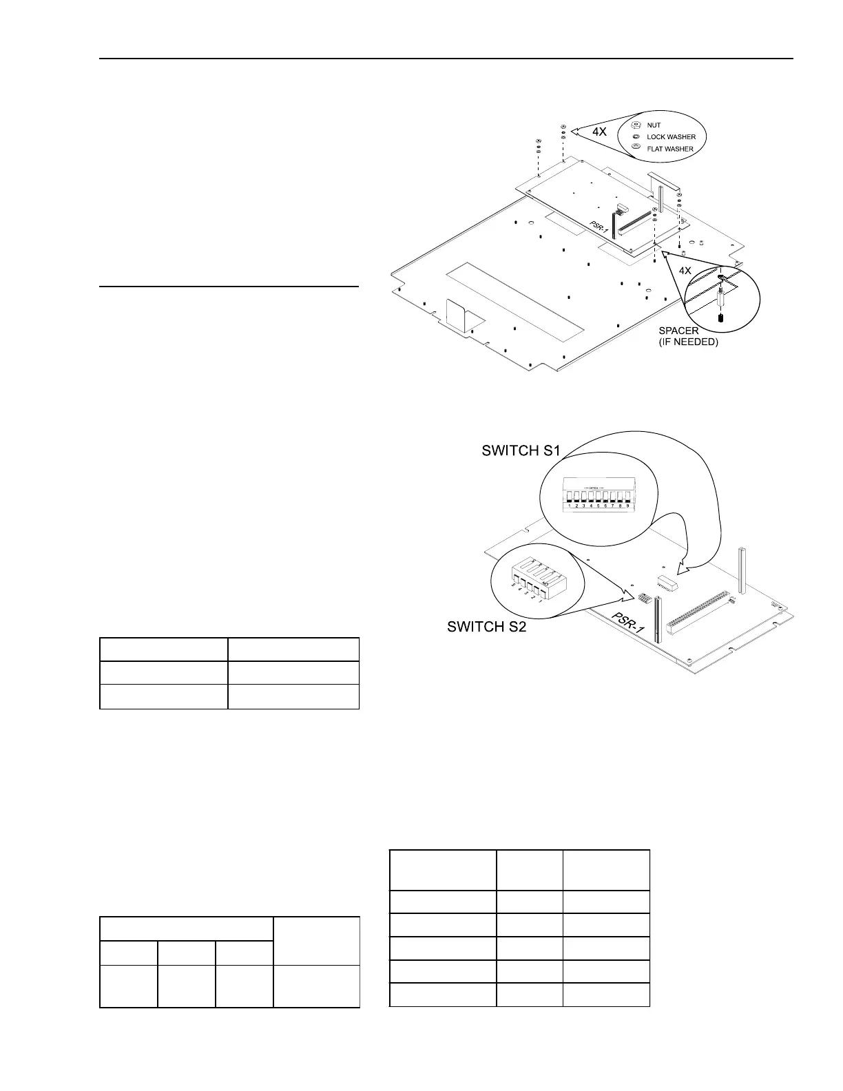
Install the PSR-1 (Remote Enclosure)
The PSR-1 Remote Power Supply
mounts on the plate where the
MMB-1/-2 would normally be mounted.
Before installing the PSR-1, set the
address on S1 and the options on S2.
Refer to the CSG-M configuration
printout for the address of the module.
Use the Network Address Program-
ming Table at the end of this chapter
to set the address for this switch.
Switch S2 , SW1 enables or disables
the network connection. Use the
Disable Network Switch Settings table
to set this switch.
DISABLE NETWORK SWITCH SETTINGS
S2-SW1 Network
Open (OFF) Enabled
Closed (ON)
Disabled*
*When not connected to the MXL network
S2, SW2/SW3/SW4 defines the maxi-
mum allowable charging current of the
battery. Use the Battery Switch Set-
tings table to set these switches. With
CSG-M Rev. 3.01 and higher, battery
sizes can be selected through software.
BATTERY SWITCH SETTINGS
DIP Switches
Charging
CurrentS2-SW2 S2-SW3 S2-SW4
Open
(OFF)
Open
(OFF)
Closed
(ON)
2.0 amps max
Installing the PSR-1 on the Mounting Plate
Switches S1 and S2 on the PSR-1
The Battery Voltage Thresholds table
defines the battery voltage thresholds
for the listed battery trouble condi-
tions. These trouble conditions are
shown on the MKB-2 Annunciator.
BATTERY VOLTAGE THRESHOLDS
Battery Status Conditions
Battery Voltage
(Volts)
Battery Not Installed <14.0
Charger Disabled <18.3
Battery Low Fault On Battery <21.0
Battery Low Fault On AC <24.0
Battery High Fault >30.0
Technical Manuals Online! - http://www.tech-man.com

 Loading...


