Electrical ratings:
5 VDC, 160mA
For battery calculations, the
NIM-1R draws 70mA from 24 VDC.
NIM-1R Network
Up to 32 MXL Systems can be con-
nected in the network with an NIM-1R
installed in each MXL System. For the
highest level of fault protection, install
the NIM-1R in the enclosure with the
MMB-1/-2, although this is not neces-
sary. When connecting more than 32
MXL Systems, a REP-1/D2300CP
repeater is required. Refer to the
REP-1 Installation Instructions,
P/N 315-092686 or the D2300CP
NIM-1R CNIM-1R C
NIM-1R CNIM-1R C
NIM-1R C
onnectonnect
onnectonnect
onnect
ions and Rions and R
ions and Rions and R
ions and R
atat
atat
at
ingsings
ingsings
ings
4 - 55
Installation Instructions, P/N 315-
092882, for the wiring diagram.
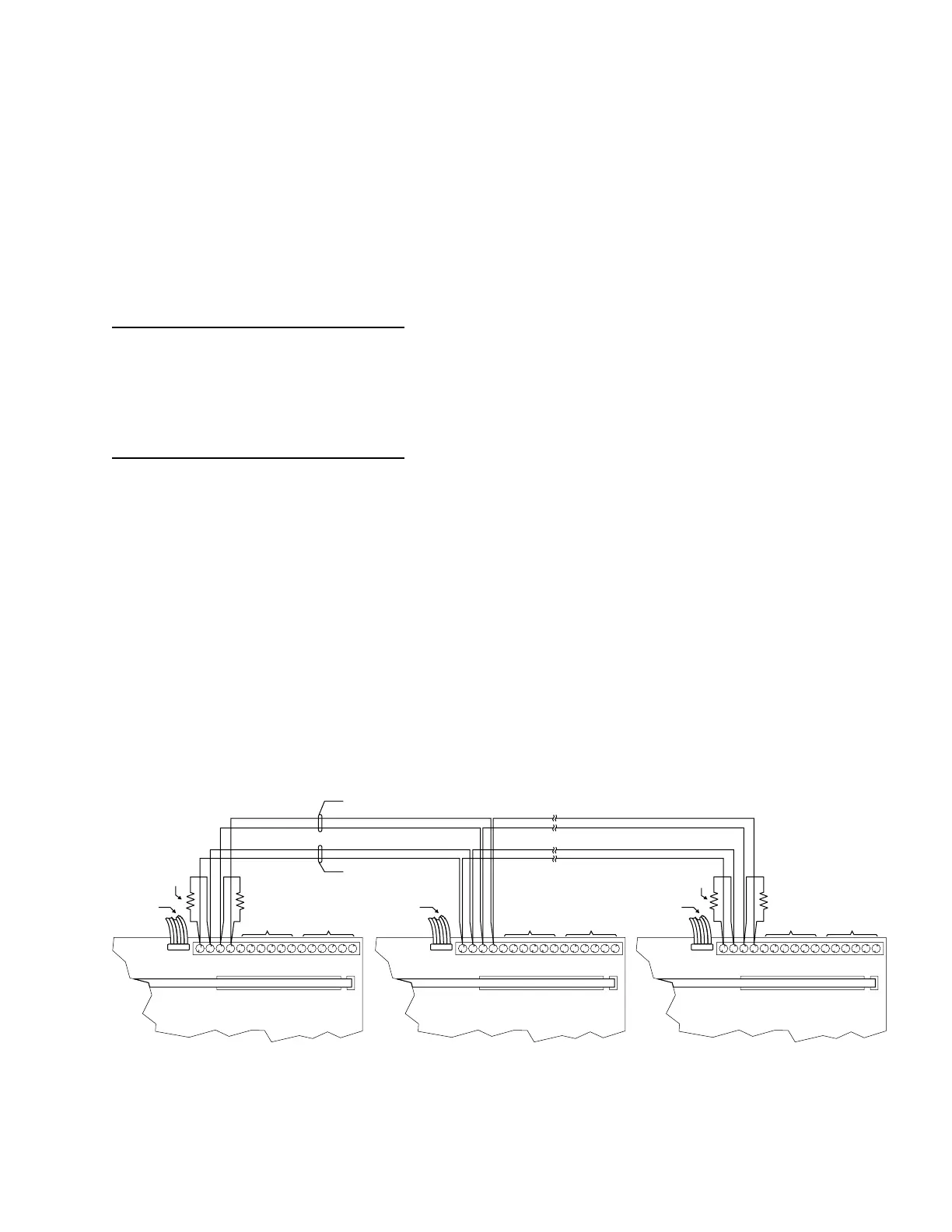
The network can be installed as either
Style 4 or Style 7. Style 7 is required
in Canada.
Each NIM-1R is shipped with two 120
ohm EOLRs—only two are required
for each network pair. Install an EOLR
at the ends of each network pair. Do
not install an EOLR at each NIM-1R.
(For a simple rule of thumb, an EOLR
must be installed where only a single
wire lands on a screw terminal.)
Do not T-tap the network wiring. If
T-tapping is required, use the REP-1/
D2300CP repeater. Refer to the
NOTES
1. Power limited to
NFPA 70 per NEC 760.
2. Minimum wire size:
18 AWG.
3. Maximum resistance:
80 ohms per pair.
4. Use twisted pair or
shielded twisted pair.
5. Terminate the shield
ONLY at MXL panel 1.
6. Maximum voltage:
8V P-P.
7. Maximum current:
150mA.
8. For Style 4 omit all
Network Pair B
connections.
9. Do not use terminals
12 - 16 if NCC is not
connected.
NIM-1R Network Wiring (Figure 1)
MOM-2/-4 MOM-2/-4 MOM-2/-4
TB3 TB3 TB3
P3 P3 P3
P7 P7 P7
1 1 12 2 2
3 3 34 4 45 5 56 6 67 7 78 8 89 9 910 10 10
11 11 1112 12 12
13 13 13
14 14 14
15 15 1516 16 16
1 1 1
NIM-1R NIM-1R NIM-1R
DO NOT
USE
DO NOT
USE
DO NOT
USE
SEE
FIGURE 2
SEE
FIGURE 2
SEE
FIGURE 2
CABLE P/N
555-190506
TO MMB-2
OR PSR-1
CABLE P/N
555-190506
TO MMB-2
OR PSR-1
CABLE P/N
555-190506
TO MMB-2
OR PSR-1
EOLR
120 OHMS, 1/4W
P/N 140-820150
EOLR
120 OHMS, 1/4W
P/N 140-820150
EOLR
120 OHMS, 1/4W
P/N 140-820150
EOLR
120 OHMS, 1/4W
P/N 140-820150
INSTALLED IN MXL PANEL 1 INSTALLED IN MXL PANEL 2 INSTALLED IN MXL PANEL 3
DO NOT USE
TB1, 1-16
DO NOT USE
TB1, 1-16
DO NOT USE
TB1, 1-16
NETWORK PAIR B
SUPERVISED (OMIT FOR STYLE 4)
*
NETWORK PAIR A
SUPERVISED
*
REQUIRED IN CANADIAN INSTALLATIONS
Technical Manuals Online! - http://www.tech-man.com

 Loading...


