2 - 38
Installation
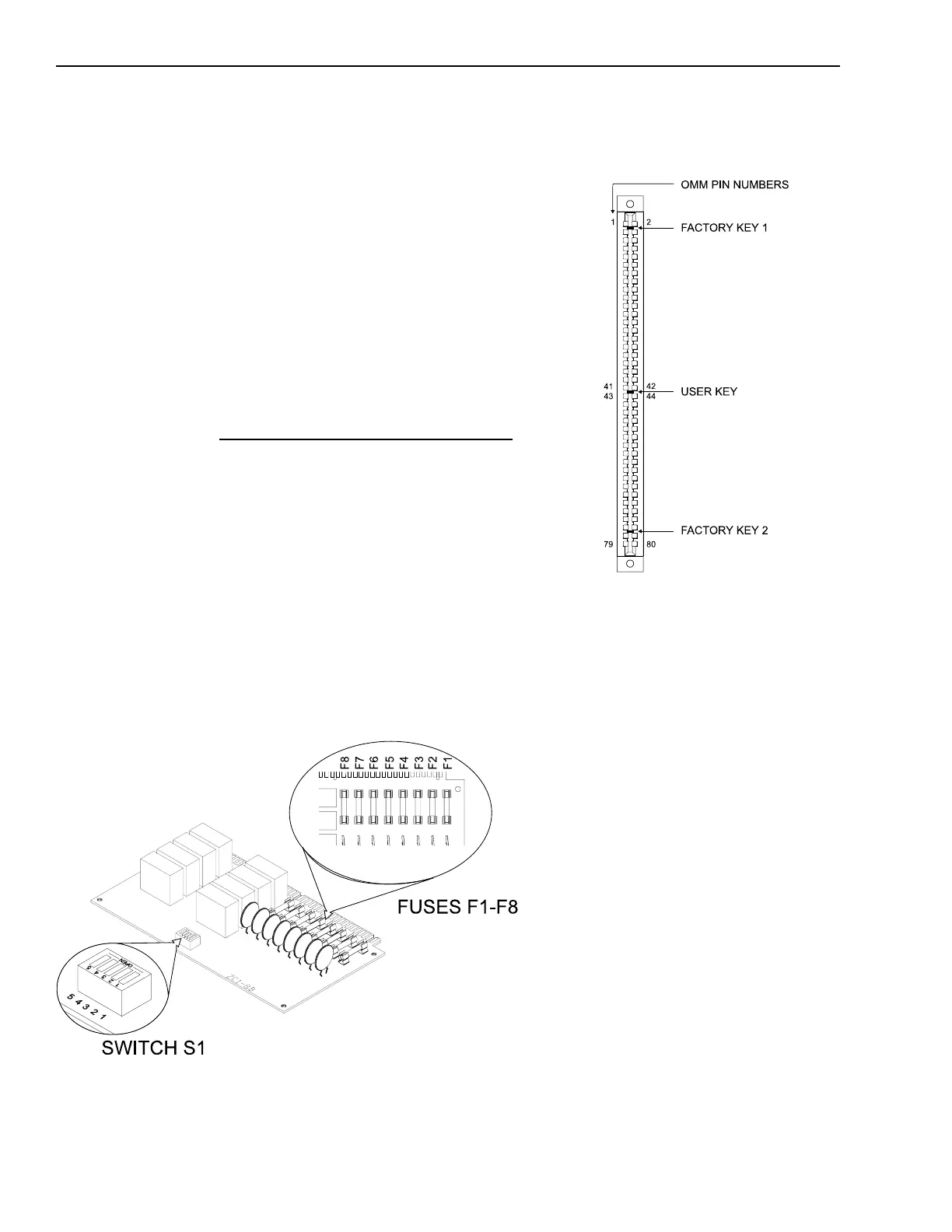
Switch S1 and Fuses F1-F8 on the ZC1-8B
Location of the User Key for the DMC-1
Place the user key from the installation
kit in the OMM-1 card edge connector
for the DMC-1 (between positions 41-
42 and 43-44).
After the address is set, install the
DMC-1 in the OMM, being sure that
the module is riding in the card guides
and is firmly seated in the card edge
connector.
Installing the ZC1-8B
The ZC1-8B plugs into a half-width slot
on the OMM and comes with an
installation kit that consists of the
following:
Eight end of line resistors,
P/N 140-820405
Three 2A, 250V fuses,
P/N 105-292199
Eight 25V fuses, P/N 105-291200
One user key
Setting the Address on the ZC1-8B
Before installing the ZC1-8B in the
OMM, set the address on S1, DIP
switches SW1-SW4. (SW5 is not used
at this time.) Refer to the CSG-M
configuration printout for the address
of the module. Use the ZC1-8B S1
Settings table to set the address for
this switch.
ZC1-8B Fuses
The ZC1-8B comes with 70V fuses,
P/N 105-291202, installed at the
factory.
For 25.2V Installations, remove the
70V fuses, F1-F8, and install the 25V
fuses, P/N 105-291200, found in the
installation kit.
Technical Manuals Online! - http://www.tech-man.com

 Loading...


