2 - 17
Installation
Installing the TMM-1 (MXLV Only)
Before installing the TMM-1, re-
move and discard any blank filler
plate that is to the right of the
MKB-2 as viewed from the front of
the panel.
Mount the TMM-1 onto the MKB-2
panel to the right side of the key-
board/annunciator display (as
viewed from the front).
From the front of the panel, insert
the TMM-1 studs through the holes
in the MKB-2 panel, and from the
rear of the panel secure the studs
with the three No. 8 nuts supplied.
Mount the electronics assembly to
the rear of the TMM-1 housing by
placing it over the four snap studs
on the side of the rear. Be sure that
the 14-pin connector (P3) is at the
bottom of the assembly. Then press
down on the board to seat it firmly.
Wiring the TMM-1
Install the cables from the module to
the paired connectors as follows:
Connect the 2-wire cable from the
hole at the rear of the telephone
housing to P2 on the left of the PC
board mounted on the TMM.
Connect the 4-wire cable provided
(P/N 600-180364) between P1 at the
top of the TMM-1 PC board and P5
on the TBM-2, which is located on
the right in the system backbox.
Connect the 14-position ribbon cable
provided (P/N 555-192236) between
P3 on the TMM-1 and P1 on the
adjacent ACM-1 module.
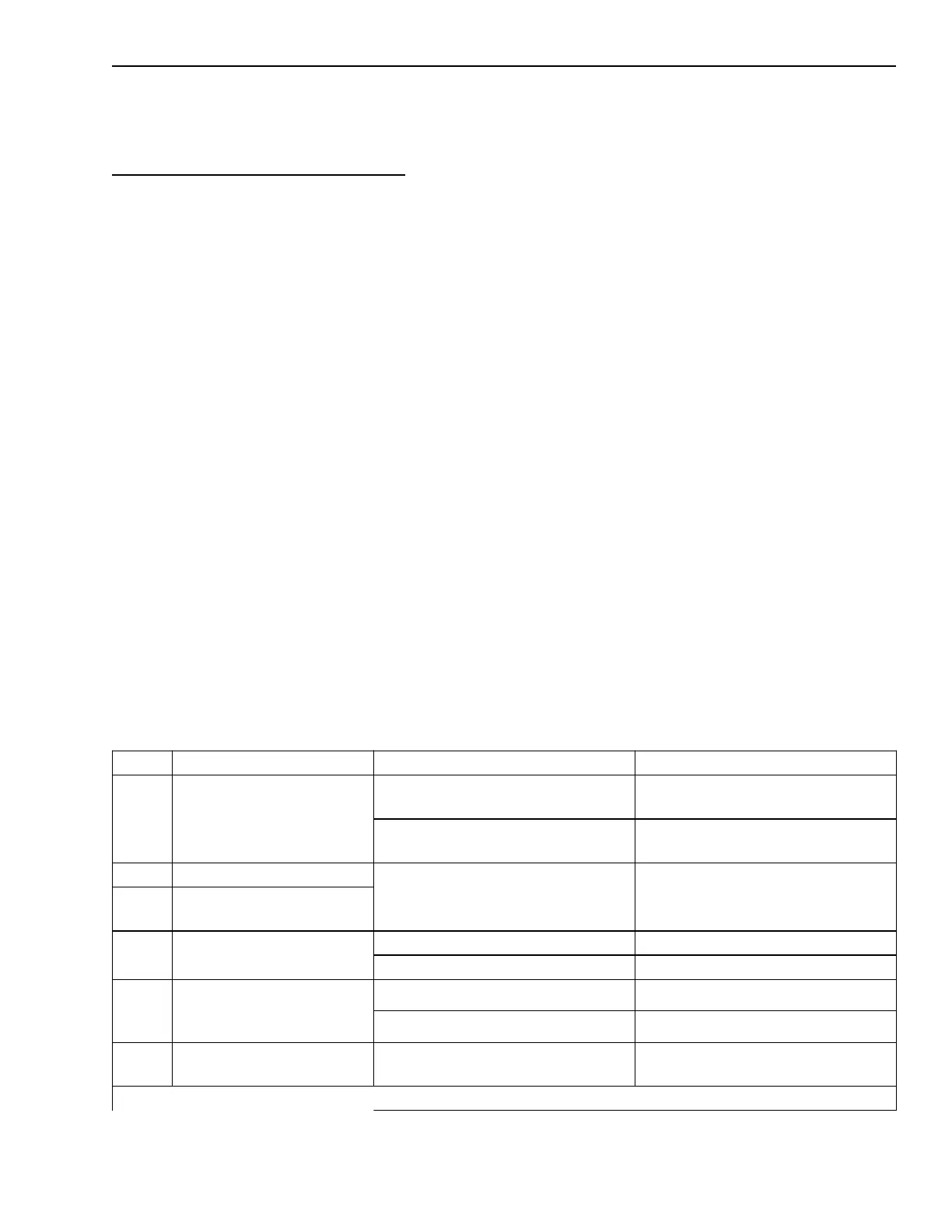
MHD PANELS
Model Purpose Location Mounting
MHD-1
Dead front barrier with cutout for
printer when needed
CONTROL PANEL*:
Use middle position (Printer available)
Place in second group of four holes by hinge
REMOTE PANEL:
Use top or middle position (No printer)
Place in first and/or second group of four holes
MHD-2 Dead front barrier only
CONTROL PANEL or REMOTE PANEL:
Use in bottom enclosure position
Place in bottom three mounting holes
MHD-2W
Dead front barrier used to mount a
DC-35S on the inside of the panel.
MHD-3
Mounting for VSM-1, VLM-1,
VFM-1, and VSB-1 modules
CONTROL PANEL*: Use in middle position Place in second group of four holes by hinge
REMOTE PANEL: Use in top or middle position Place in first and/or second group of four holes
MHD-4
A cutout for the TSP-40 printer and
with mounting for VSM-1, VLM-1,
VFM-1 and VSB-1 modules
CONTROL PANEL*: Use in middle position Place in second group of four holes
REMOTE PANEL: Use in top or middle position Place in first or second group of four holes
MHD-5
Mounting for VSM-1, VLM-1,
VFM-1 and VSB-1 modules
REMOTE PANEL ONLY:
Use in bottom enclosure position
Place in bottom three mounting holes
*CAUTION: The first group of 4 mounting holes is required for the MKB-2.
MHD PANELS
Technical Manuals Online! - http://www.tech-man.com

 Loading...


