Do you have a question about the Siemens CERBERUS PYROTRONICS PXL and is the answer not in the manual?
Introduces the PXL Conventional Fire Alarm Control Panel and its basic configuration.
Critical instructions for safe and proper system wiring, emphasizing grounding and separation.
Explains the meaning of caution and warning symbols used throughout the manual.
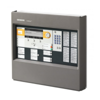
Describes the PXL Control Panel as a microprocessor-based fire protection system.
Lists the core components included in the basic PXL Control Panel.
Details components that expand the PXL system's capabilities and configuration.
Provides general installation instructions and essential guidelines before commencing.
Details the steps and considerations for securely mounting the PSE-1 enclosure.
Instructions for pulling and dressing field wiring into the enclosure.
Step-by-step guide for installing and setting the address for the PPS-10M module.
Instructions for setting the address and mounting the PRM-4 relay module.
Steps for setting the address and installing the PNC-2Z notification module.
Guidance on connecting power/data cables between installed modules in the bracket.
Detailed steps for mounting the PCM-1, including labeling and bezel placement.
Instructions for setting the address and installing the PZE-4B zone expander.
Steps for securing the PMK-1 mounting bracket within the PSE-1 enclosure.
Guidance on mounting the PTX-12 power transformer in the enclosure.
Instructions for connecting grounding straps for system safety.
Covers wiring compliance with UL-864, NEC, and separation requirements.
Details terminal connections for the PCM-1 module based on screw terminal assignments.
Details terminal connections for the PZE-4B modules based on screw terminal assignments.
Explains the user interface and system status LEDs on the PCM-1.
Describes the different system modes: Alarm, Supervisory, Trouble, Normal, Program.
Guides the user through programming functions and using the Help feature.
Provides information on firmware revisions for proper system operation.
Explains initial power-up, system configuration, and the Automatic System Configuration mode.
Outlines accessing programming options, testing, and feature descriptions.
Details configuration for AC Fail Signal Delay and Alarm Verification features.
Explains Automatic System Configuration, Control functions, and module deletion.
Covers assigning custom messages and configuring global relay operations.
Instructions for setting passcodes and the system identification.
Describes the available zone types and their default settings.
Explains the Alarm Verification feature to reduce false alarms.
Instructions for conducting walk tests to verify fire alarm system functionality.
Recommends inspection and testing schedules for system maintenance.
Lists fuse locations and their corresponding values on the PPS-10M module.
Provides a list of trouble messages, their conditions, and possible causes.
Worksheet for programming initiating device circuits and custom messages.
Worksheet for programming notification appliance circuits.
Calculates power consumption for various modules in the system.
Details electrical requirements for battery backup calculations.
Lists firmware revision requirements for Canadian system configurations.
Explains specific programming adjustments for Canadian installations.
Covers the operation and installation of the Silent Knight communicator.
Details electrical specs and wiring for the Silent Knight communicator.
Illustrates cabling connections in a PSE-2 enclosure with full module capacity.
Illustrates cabling connections in a PSE-2 enclosure with full zone and relay capacity.
| Type | Control Panel |
|---|---|
| Manufacturer | Siemens |
| Input Voltage | 120/230V AC, 50/60Hz |
| Communication Interface | RS-232, RS-485, Ethernet |
| Operating Temperature | 32°F to 120°F (0°C to 49°C) |
| Relative Humidity | Up to 93% non-condensing |


 Loading...