Appendix EPXL Conventional Fire Alarm Control Panel
73
APPENDIX E
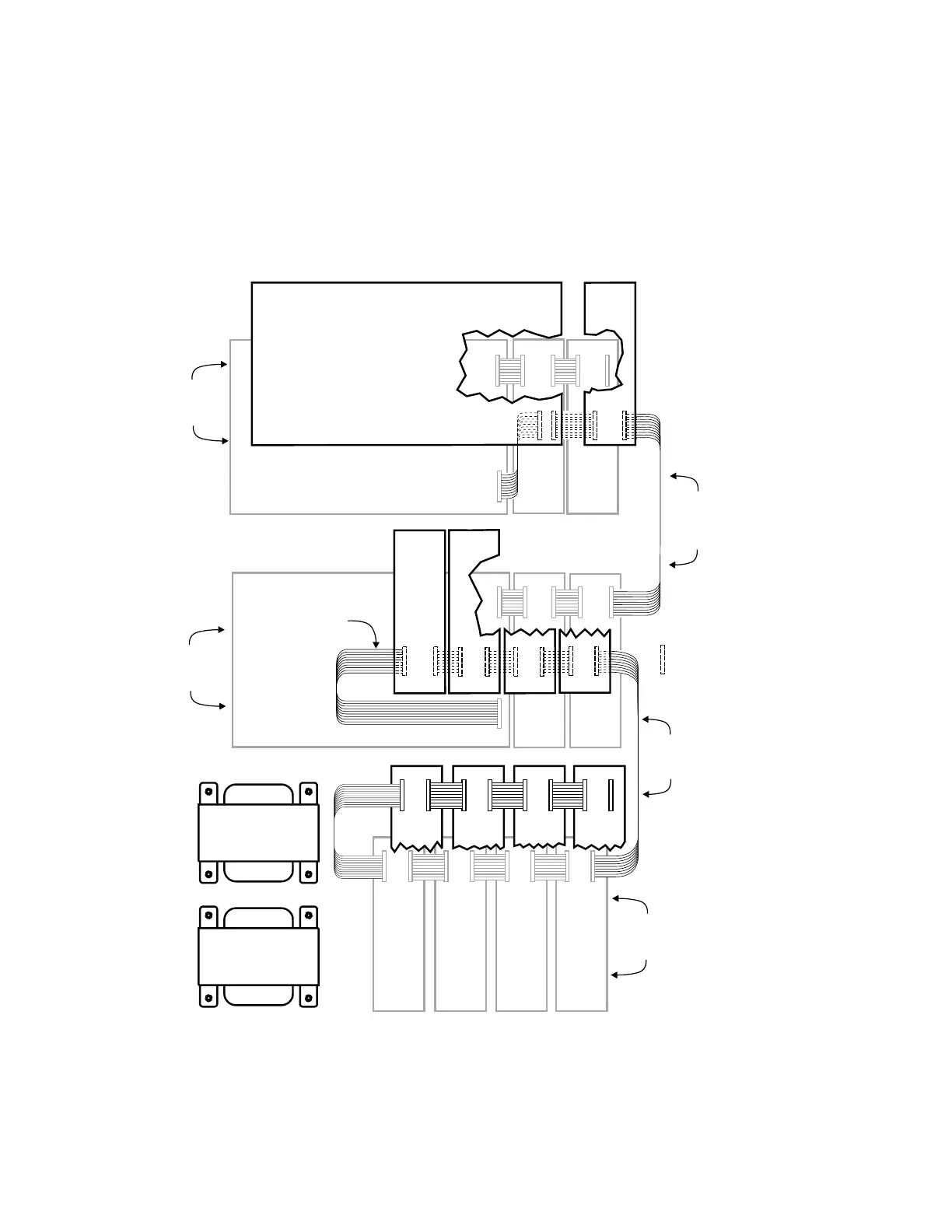
Wiring In An Expanded System
(PSE-2 Enclosure)
Figure 28
Cabling Connections in a PSE-2 Enclosure with Full Module Capacity
(Batteries Removed to BB-55/-55R)
NOTES:
1. When connecting two
PPS-10M power
supplies, the 15" cable
from the PCK-1 kit, P/N
500-695066, must have
the red wires cut and
removed.
2. When two PPS-10M
power supplies are
used in a PXL System,
cut jumper JP3 on the
second PPS-10M.
3. When two PPS-10M
power supplies are
used in a PXL System,
TB5 on the second
PPS-10M is disabled.
PPS-10M
PPS-10M
PNC-2Z
or
PRM-4
JP2
JP2
PNC-2Z
or
PRM-4
PNC-2Z
or
PRM-4
PNC-2Z
or
PRM-4
JP2
JP2 JP2
JP1JP1
JP1
JP1
JP2
JP2 JP2JP1
PZE-4B
PZE-4B
JP7
= Components are
underneath the board
1
1
1111
JP7
JP6
JP6
PZE-4B
JP1JP1
1
1
1
1
1
1
111
11
1
1
PNC-2Z
or
PRM-4
PNC-2Z
or
PRM-4
PNC-2Z
or
PRM-4
PNC-2Z
or
PRM-4
PNC-2Z
or
PRM-4
PNC-2Z
or
PRM-4
PNC-2Z
or
PRM-4
PNC-2Z
or
PRM-4
15" CABLE FROM
PCK-1 KIT (P/N 500-695066)
WITH RED CONDUCTORS
CUT AND REMOVED
MOUNTED ON
FIRST PMK-1
BRACKET
MOUNTED ON
SECOND PMK-1
BRACKET
MOUNTED
ON PMK-2
BRACKET
PTX-12
TRANSFORMER
15" CABLE FROM
PCK-1 KIT (P/N 500-695066)
WITH ALL CONDUCTORS
CABLE P/N
555-194066
(Provided with
the modules)
-
JP1
JP1 JP1 JP1 JP1
JP1 JP1 JP1JP2
JP2 JP2 JP2 JP2
JP2 JP2 JP2
PZE-4B PZE-4B
JP7
JP6
JP7
JP6
JP7
JP6
JP7
JP6
PCM-1
11 11 11
11111111
11
1
1
1
1
11
PTX-12
TRANSFORMER
Technical Manuals Online! - http://www.tech-man.com
 Loading...


