InstallationPXL Conventional Fire Alarm Control Panel
27
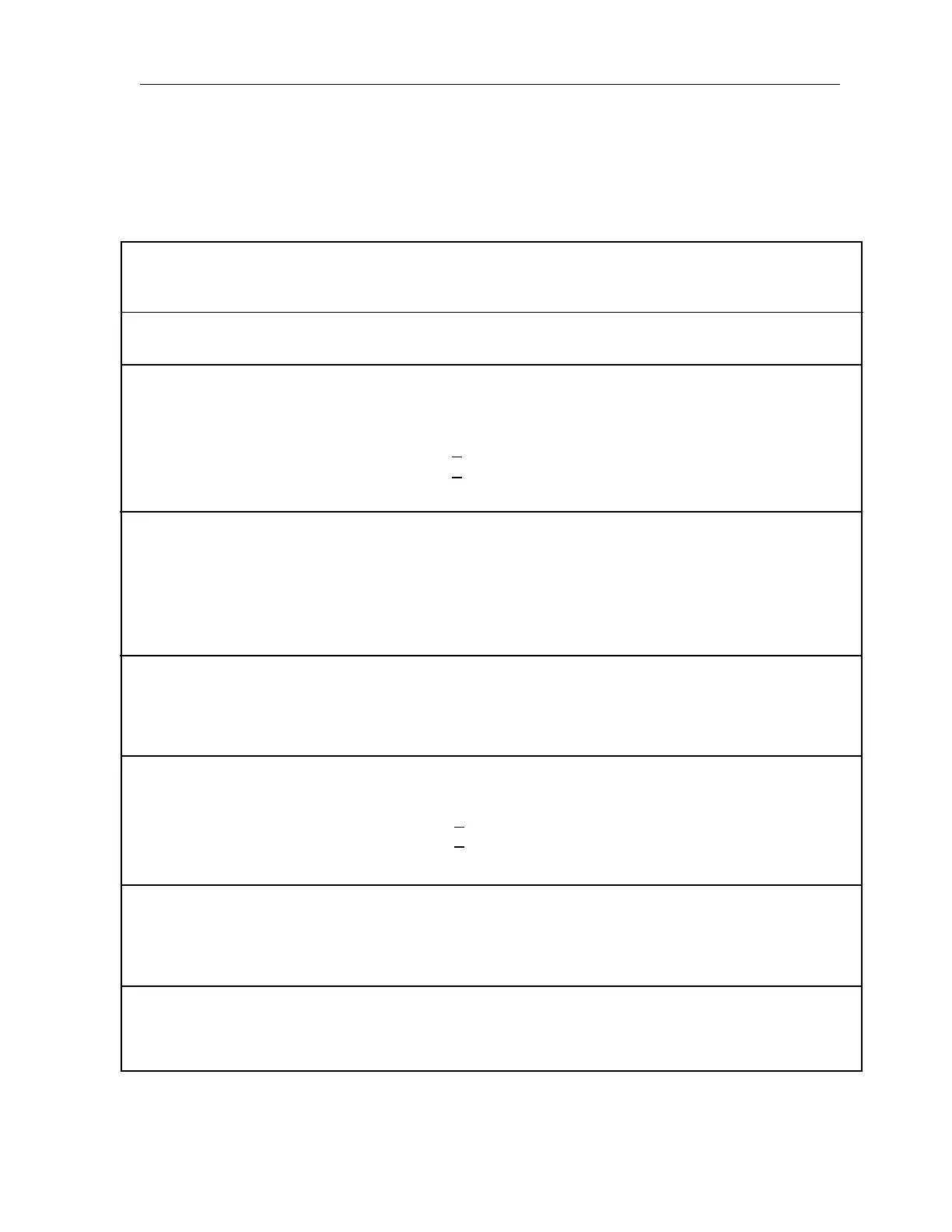
Measure Resistance
Between
Terminal and Terminal Desired Results Probable Cause if Results Differ
For Steps 1 and 2, connect positive lead of meter to F+ and negative lead to F- of the Notifi-
cation Appliance Circuit to be tested. Repeat for all Notification Appliance Circuits.
1. Measure Notification Appliance Circuit Loop Resistance
Remove 10K End of Line Resistor and short end prior to measurement.
NAC Maximum Current
Up to 1.5A <3.0 ohms Line open
>1.5 to 2.0A
<2.5 ohms Line too long
Wire gauge too small
2. Measure Notification Appliance Circuit End of Line Resistance
Reconnect End of Line Resistor device prior to measurement.
10K ohms Line shorted; Line open
Incorrect EOLR value
NAC device wired backward
NAC device not polarized
3. Check for Notification Appliance Circuit Ground Fault
Measure between:
F+ and ground >1 megohm Line shorted
F- and ground >1 megohm Line shorted
4. Measure Initiating Device Circuit Loop Resistance
Remove the 3.9K End of Line Resistor and short end prior to measurement.
IDC with relay or audible base <40 ohms Line open
IDC without relay or audible base
<70 ohms Line too long
Wire gauge too small
5. Measure Initiating Device Circuit EOL Resistance
Reconnect the EOL device prior to measurement.
3.9K ohms Line shorted; Line open
Incorrect EOLR value
6. Check for Initiating Device Circuit Ground Fault
IDC+ >1 megohm Line shorted
IDC- >1 megohm Line shorted
*Do not connect field wiring to terminals during checkout procedure.
TABLE 5
FIELD WIRING CHECKOUT PROCEDURE*
{
{
Technical Manuals Online! - http://www.tech-man.com
 Loading...


