Do you have a question about the Siemens QAA75.611 and is the answer not in the manual?
Engineering, mounting, dimensions, and drilling plan for the main unit.
Details of connection terminals and their markings for the RVS61.843.
Mounting method, connections, dimensions, and panel cutout for the operator unit.
Connections and dimensions for the AVS37.390 operator unit.
Engineering, mounting, connections, dimensions, and drilling plan for the QAA55 room unit.
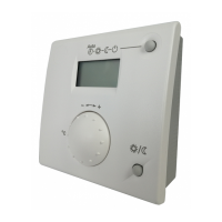
Engineering, mounting method, and connections for the QAA75 room unit.
Engineering, mounting, connections, radio connection, and dimensions for the QAA78 room unit.
Mounting method, connections, and radio connection for the wireless outside sensor.
Steps for commissioning the RVS61.843, including checking LED status.
Operation of room units and operator units, including descriptions of operating elements.
Details of operating elements for room units and operator units, explaining their functions.
How to switch between operating modes like Automatic and Continuous for space heating.
How to select and operate the cooling mode, including its characteristics.
How to activate and deactivate DHW heating mode, including DHW push function.
How to adjust the comfort and reduced room temperature setpoints using the control knob.
How to perform manual defrost or reset functions using the RESET button.
Principles of programming settings via menus and operating lines, with an example.
How to access different user levels (Enduser, Commissioning, Heating engineer) for settings.
A comprehensive table outlining available settings, operating levels, and default values.
Details on operator section settings including language, info, operation lock, and programming lock.
Procedures for binding wireless devices, testing radio links, and listing RF devices.
Process of assigning wireless peripheral devices to the basic unit for system commissioning.
Setting up switching programs for heating circuits and DHW, including preselection and default values.
Functions available for individual heating circuits, including operating mode and setpoints.
Adjusting heating curves to match flow temperature to weather conditions for optimal heat output.
Adjusting curve steepness to influence flow temperature based on outside temperatures.
Accelerating heating to reach new setpoints faster, shortening heat-up times.
Function to reduce heating temporarily, with options for room sensor or time-based control.
Optimizing start/stop times to reach setpoints efficiently.
Adjusting the reduced setpoint to prevent excessive cooling and shorten heat-up times.
Controlled drying of floors using temperature profiles, with automatic or manual settings.
Operating cooling circuits, including mode selection, setpoints, and release criteria.
Selecting the operating mode (Off, Automatic) for cooling circuits.
Determining required flow temperature for cooling based on outside temperature and defined points.
Releasing or locking cooling based on composite outside temperature thresholds.
Defining minimum flow temperature limits for cooling based on outside temperatures.
Compensating room temperature deviations for accurate control, with different methods.
Deactivating cooling pump if room temperature falls below setpoint, considering summer compensation.
Settings for mixing valve decrease, actuator type, switching differential, and running time.
Preventing condensation by controlling flow temperature based on humidity and dewpoint.
Configuring buffer storage tanks and primary controllers for cooling circuits.
Enabling DHW heating based on 24h/day, time programs, or DHW release.
Setting priority for DHW charging over space heating based on heat source capacity.
Settings for periodic or weekday legionella function to prevent bacteria growth.
Defining if Hx circuits can draw heat from the buffer storage tank.
Determining if primary controller/system pump impacts the consumer group.
Configuring primary controller or system pump installation relative to the buffer storage tank.
Settings for condenser pump operation related to frost protection, temperature requests, and compressor activity.
Functions preventing low source temperatures and ensuring source temperature stability.
Compressor control based on return temperature and switching differentials.
Compressor control using buffer/storage tank sensors and minimum running times.
Settings for compressor run times, switch-off temperatures, and startup delays.
Observing minimum compressor running time when heat request is stopped.
Minimum operating time for the compressor after switching on.
Minimum time the compressor remains switched off.
Switching off the compressor if flow or return temperature exceeds maximum.
Reduced switch-off temperature for DHW charging or forced buffer charging.
Settings for locking compressor stage 2 during DHW charging and release conditions.
Releasing second stage based on integral values and heat deficits.
Automatic changeover of compressors to equalize operating hours.
Control of electric immersion heaters using relay outputs and sensors.
How the electric immersion heater is used in different modes like substitute or emergency operation.
Conditions where electric immersion heater use has no impact or is complemented by HP operation.
Time delay for switching on the electric immersion heater after compressor startup.
Releasing stages of electric immersion heater based on integral values and heat deficits.
Protection measures for the heat pump during DHW charging, including charging attempts and temperature monitoring.
Compensation for heat deficits and excess heat, with behavior during floor curing.
Compensating for heat deficits and excess heat, with specific behavior during floor curing.
Setting the number of DHW charging attempts before abortion or electric heater activation.
Action taken when a 3-phase current error persists for a set period.
Action taken when flow switch signals persist, potentially leading to lockout.
Releasing the heat pump based on composite outside temperature for bivalent operation.
Behavior of the heat pump during forced buffer storage tank charging.
Behavior of the heat pump during full buffer storage tank charging.
How defrosting is achieved using fan or process reversal for air-to-water heat pumps.
Automatic defrost activation based on temperature differences and timing parameters.
Manual triggering of defrost via inputs or operating lines.
Conditions for releasing defrost based on source inlet temperature relative to a setpoint.
Setting the maximum number of defrost attempts before heat pump lockout.
Time period after which the next defrost attempt can be initiated.
Prerequisite for defrosting based on source temperature and preheating period.
Maximum duration for a defrost process, with retry logic.
Releasing the heat pump based on flow/return temperature falling below a threshold.
Operating the heat pump in active cooling mode using a process reversing valve.
Heat pump operating as a refrigeration machine, requiring specific system diagrams.
Cooling using cold water circulation without a refrigeration source.
Preventing compressor operation if return temperature exceeds maximum cooling switch-off temperature.
Minimum source temperature setting to prevent ice formation in passive cooling.
Switching to passive cooling if source temperature drops below cooling setpoint.
Adjusting return temperature setpoint for active cooling based on cooling curve and set value.
Settings for managing heat sources in a cascade system, including integral release and switch-on delay.
Settings for managing heat sources in a cascade system, including integral release and switch-on delay.
Using solar energy for swimming pool heating and DHW/buffer charging, with priority selection.
Controlling solar charging based on temperature differentials and minimum collector temperatures.
Setting priority for solar charging of swimming pools over storage tanks.
Activating the collector pump to prevent freezing when frost risk is detected.
Continuing storage tank charging to reduce excess heat and stopping when safety temperature is reached.
Integrating buffer storage tanks for heating, cooling, and DHW charging.
Triggering forced charging to save electricity or fully charge the tank before heat pump lockout.
Locking the heat source based on buffer storage tank temperatures and differentials.
Controlling DHW temperature, priority, and legionella function, with criteria for abortion.
Making DHW requests to heat sources based on setpoint boost, transfer boost, and charging types.
Charging DHW until maximum temperature is reached, with collector pump reactivation.
Operating modes and release conditions for electric immersion heaters in DHW systems.
Control methods for electric immersion heaters using external thermostats or DHW sensors.
Configuring buffer storage tanks and solar integration for DHW systems.
Supporting DHW heating via external heat exchangers with speed-controlled pumps and mixing valves.
Supporting DHW heating via external heat exchangers with speed-controlled pumps and mixing valves.
Defining minimum setpoint difference to tank temperature for instantaneous DHW heaters.
Setting minimum pump speed for instantaneous DHW heaters.
Steps for configuring the system by selecting and adjusting plant diagrams and parameters.
Steps for configuring the system by selecting and adjusting plant diagrams and parameters.
Preselecting plant diagrams using a number and connecting sensors for correct identification.
Manually creating or adjusting plant diagrams using available partial diagrams and catalogs.
Enabling heating and cooling circuits, and configuring mixing valve usage.
Setting the DHW control element to charging pump or diverting valve.
| Protection Class | IP30 |
|---|---|
| Number of Channels | 1 |
| Type | Room controller |
| Power Supply | 24 V AC/DC |
| Temperature Range | 0 to 50 °C |
| Operating Temperature | 0 to 50 °C |
| Humidity Range | 0 to 95 % |
| Mounting | Wall mounting |
| Sensing Element | NTC |
| Setpoint Setting Range | 5 to 30 °C |
| Contact Configuration | SPDT |
| Standards | EN 60730 |
| Voltage Rating | 24 V |


