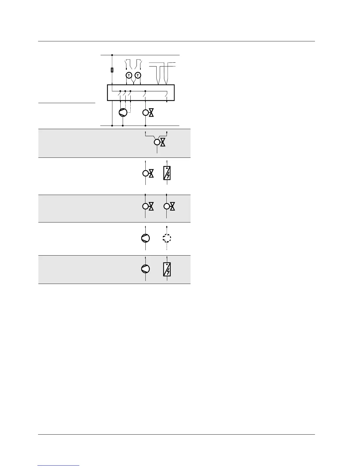
EasyManua.ls Logo

Siemens RDF301

Siemens RDF301
17 pages
To Next Page IconTo Next Page
To Previous Page IconTo Previous Page
Loading...
Connection diagrams
Application
N1 Room thermostat
RDF301... , RDF600KN
M1 1- or 3-speed fan
Y1 Valve actuator, 2- or 3-position
Y1, Y2 Valve actuator, 2-position
E1 Electric heater
C1, C2 1-stage compressor
F External circuit breaker
S1, S2 Switch (keycard, window contact,
presence detector, etc.)
B1, B2 Temperature sensor (return air
temperature, external room
temperature, changeover sensor, etc.)
CE+ KNX data +
CE- KNX data
2-pipe, 2-position
2-pipe, 3-position
Y11 = Open
Y21 = Close
2-pipe and electric
heater
4-pipe
Y1 = Heating
Y2 = Cooling
1-stage compressor
C1 = Heating
and / or
C2 = Cooling)
1-stage compressor
and electric heater
L
N
10 A
L
N
Y11
Y21
AC 230 V
X1 M
X2
N1
M1
Y1
5(2)A
max.
5(2)A
max.
B2
S2
B1
S1
F
3171A12
Q1 Q2 Q3
I II III
CE+ CE-
KNX
Y1
5(2)A
max.
E1
5(2)A
max.
5(2)A
max.
Y1
C1
5(2)A
max.
Y1
5(2)A
max.
Y2
5(2)A
max.
C1
5(2)A
max.
E1
5(2)A
max.
C2
5(2)A
max.
16 / 17
Siemens RDF301, RDF301.50..., RDF600KN CE1N3171en
Building Technologies Semi flush-mount communicating room thermostats 2014-05-23

Other manuals for Siemens RDF301

Related product manuals