RDF30U Room Temperature Controller with LCD Technical Instructions
For Four-Pipe Fan Coil Units Document Number 155-335
September 27, 2007
Siemens Industry, Inc. Page 7
Table 3. DIP Switches.
Position ON (Factory Setting)
Fan control is temperature-
independent in Normal mode
Fan control is temperature-
dependent in all operating
modes
Display of temperature or setpoint
Room (or return air) temperature
display
Operating action of switch for external
operating mode changeover
Changeover activated when switch is
closed
Changeover activated when
switch is open
Heating and cooling (four-pipe)
Mounting,
Installation and
Commissioning
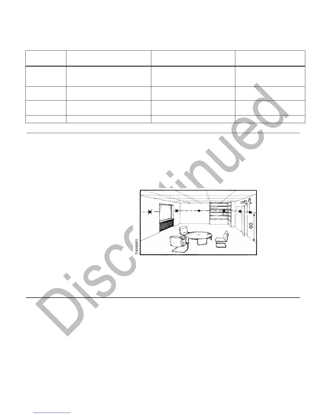
Notes
▪ Mounting location: On a wall or inside the fan coil unit.
▪ Do not mount in niches or bookshelves, behind curtains, above or near heat
sources.
▪ Do not mount in direct sunlight.
▪ Mounting height is approximately 60 inches (1.5 m) above the floor.
▪ The connecting wires can be run to the controller from a recessed conduit box.
Figure 3. Acceptable Mounting Height in Inches.
▪ Check the positions of the DIP switches and change them, if required.
▪ After applying power, the controller makes a reset during which all LCD segments
flash, indicating that the reset has been correctly made. This takes about three
seconds. Then, the controller is ready to operate.
 Loading...