Do you have a question about the Siemens RDE10 Series and is the answer not in the manual?
Illustrates the control loop of the room temperature controller with switching differential.
Details normal operation, energy saving mode, and 7-day time switch functionality.
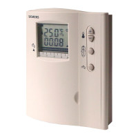
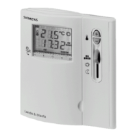
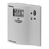
Explains the digital display contents and symbols for operating modes and heating status.
Describes retention of setpoints during power failures or battery changes.
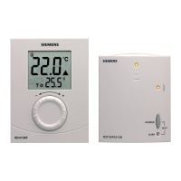
Lists controller types (RDE10, RDE10.1) and ordering information.
Details compatible actuators and their references for system integration.
Lists available adapter plates for installation and their references.
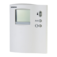
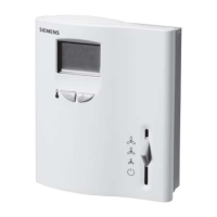
Describes the two-part construction: housing with display and mounting base.
Identifies and explains the function of numbered components on the controller.
Provides guidelines for optimal location, mounting, and electrical connections.
Covers sensor calibration, battery replacement, and system reset procedures.
Details operating voltage, power consumption, and control output ratings.
Specifies setpoint ranges, switching differential, and display resolution.
Lists climatic, mechanical conditions, EMC, and safety class requirements.
Specifies connection terminals, weight, and housing color.
Illustrates wiring for RDE10 and RDE10.1 models.
Shows typical system configurations for boilers and floor-standing boilers.
Provides overall physical dimensions for the controller unit.
Details the dimensions and mounting hole layout of the baseplate.
Shows a connection diagram for controlling a heating circuit pump with a mixing valve.
| Brand | Siemens |
|---|---|
| Model | RDE10 Series |
| Category | Temperature Controller |
| Language | English |