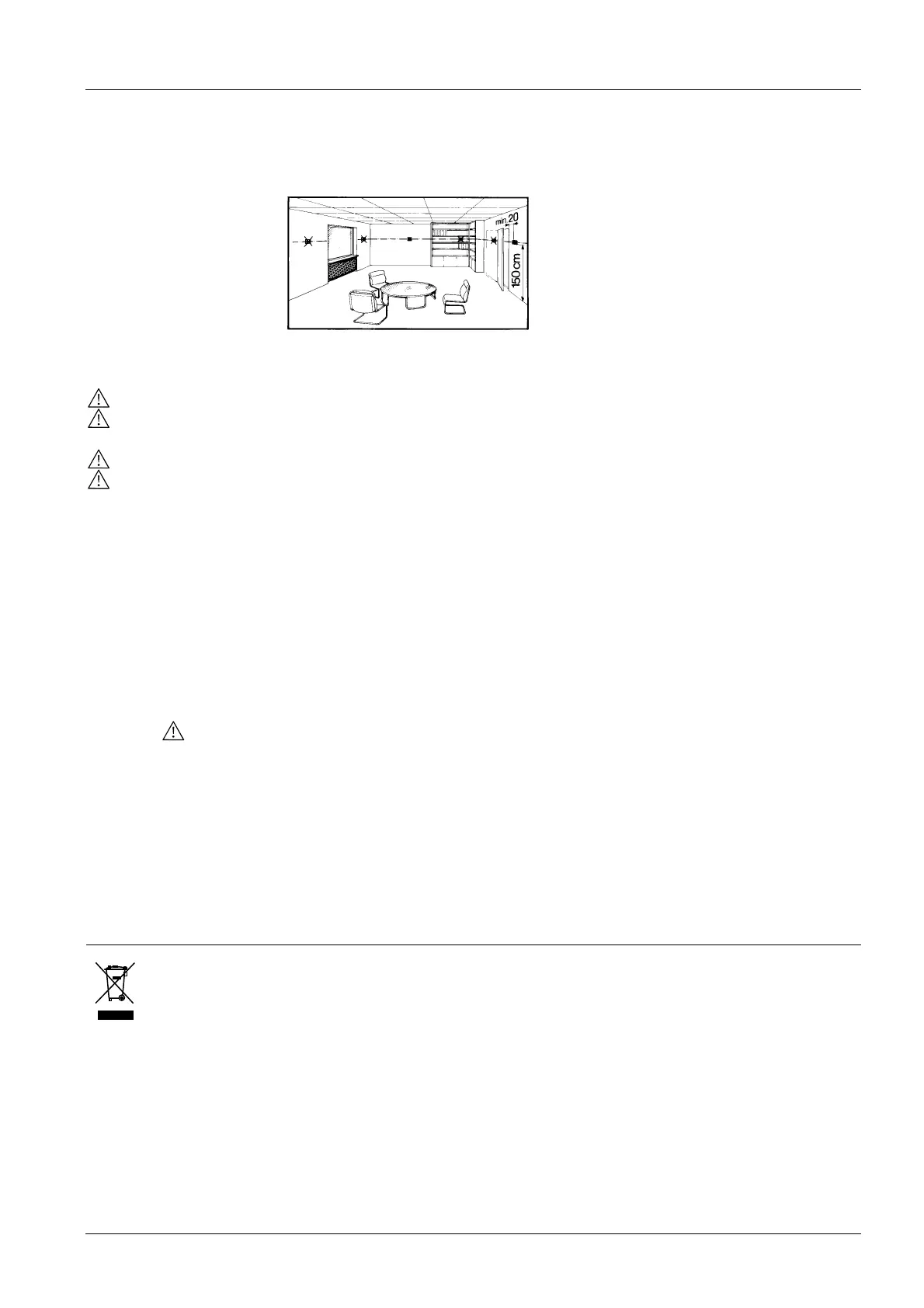
Mounting and installation
The room controller can be mounted on a recessed rectangular conduit box with fixing
centres of 60.3mm. The mounting location on a wall should not be in niches or book-
shelves, not behind curtains, above or near heat sources and not exposed to direct
solar radiation. Mounting height is about 1.5 m above the floor.
Also refer to the Mounting Instructions B3067 enclosed with the controller.
Wiring
• Wiring, fuse and earthing must be installed in compliance with local regulations.
• The cables to the controller, fan and valves carry AC 230 V mains voltage and must
be appropriate sized
• Only valves rated for AC 230 V may be used
• The AC 230 V mains supply line must have an external fuse or circuit breaker with a
rated current of no more than 10 A
After applying power, the controller makes a reset during which all LCD segments flash,
indicating that the reset has been correctly made. This takes about 3 seconds. Then,
the controller is ready for commissioning by qualified HVAC staff. The control parame-
ters of the controller can be set to ensure optimum performance of the whole system
(also refer to “Setting the control parameters”).
Commissioning
• Depending on the application, the heating / cooling mode must be set via parameter
P22. Factory setting is “Manual heat/cool changeover”. When using in ”Cooling
only” or “Heating only”, P22 must be set accordingly.
Heating / cooling mode
• If the controller is used in conjunction with a compressor, the minimum output on
time (parameter P15) and off time (parameter P16) of Y11 must be adjusted in order
not to harm the life time of the compressor
Compressor-based
application
• If the room temperature displayed by the controller dos not accord with the room
temperature effectively measured, the temperature sensor can be recalibrated. In
that case, parameter P07 must be changed
Calibrating the sensor
• For comfort and energy saving reasons, it is suggested to review the setpoints and
setpoint ranges (parameters P01…P06) and, if necessary, to change them
accordingly
Setpoint and range
limitation
Disposal
The controller includes electrical and electronic components and must not be disposed
of as domestic waste.
Current local legislation must be observed.
11/14
Siemens Room Temperature Controllers N3067en
Building Technologies 01.10.2007
 Loading...