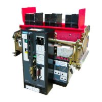
Do you have a question about the Siemens RL and is the answer not in the manual?
Instructions on locating, identifying, and ordering replacement parts.
Mechanically operated counter that mounts on the auxiliary switch.
Manual charging handle assembly for maintenance tool use.
Solenoid device that must be energized before breaker can be closed.
Automatically trips breaker on loss of voltage; instantaneous or time-delay.
Switch indicating breaker trip flap position, used with interlocks.
Trip device mounting onto a slide-type bracket on the circuit breaker.
Operates a switch to provide a lockout feature to prevent reclosing.
Manual reset for tripping actuator, disabling automatic reset.
Procedures for checking and cleaning the fuse carriage for reliable service.
Procedure for testing the open fuse trip attachment's voltage operation.
Integral key-operated interlock for cubicle location preventing unsafe racking.
Step-by-step guide for installing the fuse carriage and circuit breaker.
Specifies special purpose fuses required for circuit breaker/fuse carriage combination.
Details on trigger fuses used for phase indication and open fuse trip functionality.
Describes fuse carriages for RLF-3200 and RLF-4000 circuit breakers in switchgear.
Details RL-3200 and RL-4000 unfused circuit breaker ratings and fuse carriage features.
Safety guidelines for operating RLF circuit breakers with RFC fuse carriages.
Mechanism that opens the breaker when a current-limiting fuse opens.
Used to increase interrupting capacity beyond breaker alone or limit fault current.
Functions to trip breaker, indicate phase interruption, and retain trip-free position.
Details specific lubrication points and recommended lubricants for breaker parts.
Recommendations for applying lubricants to bearing pins and contact surfaces.
Switches controlling motor operation for electrically operated breakers.
Instructions for connecting and testing static trip devices after replacement.
Procedures for checking and adjusting main and arcing contact make.
Details on tripping actuator function, replacement, and troubleshooting.
Procedure for performing maintenance closing operation to check mechanism.
Checking and setting connected position alignment of the racking mechanism.
A suggested procedure for routine maintenance and lubrication sessions.
Safety practices and references for maintenance personnel.
Defines service conditions and intervals based on ANSI standards.
Guidance on removing old grease and applying new lubricants.
Step-by-step guide for annual inspections of RL circuit breakers.
Interlocks preventing racking of a closed breaker or opening springs charged.
Sequence for racking the circuit breaker into the cubicle.
Ensures springs discharge when racking breaker out to DISCONNECTED position.
Details on the operation of manually charged RL circuit breakers.
Describes the operation of electrically charged RL circuit breakers.
Illustrates and labels the components of the circuit breaker operator mechanism.
Details continuous and interrupting ratings and fused breaker configurations.
Important safety precautions before operating the circuit breaker.
Guidance on safely attaching lifting bars and positioning circuit breakers.
Steps for inserting the circuit breaker into the cubicle and testing.
Checking the operation of interlocks for drawout circuit breakers.
Checking control wiring and performing insulation tests after installation.
Procedures for inspecting equipment for damage upon receipt.
Requirements for installing breakers in clean, dry, well-ventilated areas.
Recommendations for storing circuit breakers indoors or outdoors.
Checks required before placing circuit breaker in compartment.
Defines a qualified person with familiarity and training for equipment.
Defines 'Danger', 'Warning', and 'Caution' signal words used in the manual.
General safety rules to follow during maintenance and operation.
Information on obtaining technical guidance from Siemens Field Service.
Diagram and list of parts for RL Breaker Assembly (Part 1).
Detailed part numbers and usage for RL Breaker Assembly (Part 1).
Diagram of RL Breaker Assembly (Part 2).
Detailed part numbers and usage for RL Breaker Assembly (Part 2).
Diagram continuation of RL Breaker Assembly (Part 2).
Detailed part numbers and usage for RL Breaker Assembly (Part 2).
Diagrams and part lists for contacts of RL-3200 and RL-4000 breakers.
Diagrams and part lists for contacts of RL-800 to RL-2000 breakers.
Diagrams and part lists for the circuit breaker operator mechanism.
Diagrams and part lists for the motor group assembly.
Detailed part numbers and usage for the motor group.
Diagram and part list for the close solenoid group.
Diagram and part list for the old style anti-pump 'Y' relay.
Diagram and part list for the new style anti-pump 'Y' relay.
Diagram and part list for the shunt trip group.
Diagram and part list for the blown fuse trip assembly.
Diagram and part list for the open fuse indicator.
Diagram and part list for the trigger fuse assembly.
Diagrams and part lists for drawout secondary disconnect groups.
Diagram and part list for the complete undervoltage device.
Diagrams and part lists for various auxiliary switch groups.
Diagrams and part lists for optional bell alarm switch groups.
Diagram and part lists for the Static Trip III group.
Diagrams and part lists for tripping transformer groups.
Diagrams showing tapped sensor connections for dual winding configurations.
Diagram and part list for communications options.
Diagram and part list for integrally fused breakers.
Diagram showing the outline of the fuse carriage.
Diagram showing key interlock mounting for fuse carriages.
Diagram and part list for the open fuse sensor.
Diagram and part list for the open fuse sensor.
| Rated Voltage | 250VAC, 30VDC |
|---|---|
| Mechanical Life | 10, 000, 000 operations |
| Operating Temperature Range | -40°C to +70°C |
| Contact Configuration | SPDT |
| Contact Rating | 10A |
| Electrical Life | 100, 000 operations |
| Mounting Type | PCB |


