Do you have a question about the Siemens SAS61.03U and is the answer not in the manual?
Explains the document's chapter structure and orientation.
Details changes made across different document versions.
Lists related documents and their types.
Provides preliminary information before using the product.
Lists third-party trademarks and their legal owners used in the document.
Outlines terms for duplicating and distributing the document.
Describes the care taken in document preparation and revision.
Advises users to read related documents and assumes user training.
Defines the document's purpose and target audience.
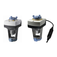
Introduces the line of stroke actuators SAS.. and SAT.. and their components.
Summarizes the different stroke actuator types with their specifications.
Provides information on how to order actuators and associated components.
Details compatible valve and actuator combinations for different applications.
Lists available electrical and mechanical accessories for the actuators.
Guides on replacing older SQS/SSC actuators with SAS/SAT models.
Lists available spare parts for the actuators.
Covers actuator sizing considerations, including parallel operation and cable selection.
Outlines warranty conditions related to valve compatibility.
Provides instructions for mounting and installing the actuators.
Illustrates acceptable indoor and outdoor mounting orientations.
Details the process of attaching stroke actuators to threaded valves.
Explains special notes and steps before fitting accessory items.
Provides step-by-step guide for installing the ASC10.51 auxiliary switch.
Explains how to fit the weather shield for outdoor use.
Covers electrical connection procedures and preparation of wire endings.
Details the process of checking functions and calibrating the actuator.
Provides notes on electrical calibration for specific actuator types.
Explains how to perform a point test for the auxiliary switch.
Guides on commissioning actuators using Modbus RTU communication.
Describes full and partial configuration of actuators via bus.
Details how to use the user interface and operate the actuator via pushbutton.
Explains LED color codes and how to set the Modbus address using pushbuttons.
Provides examples for setting Modbus addresses using the pushbutton.
States that actuators are maintenance-free and provides mounting precautions.
Provides safety warnings and guidelines for disposing of the device.
Explains the operation of actuators using 3-position control signals.
Discusses positioning times and stroke model characteristics.
Details actuator compatibility with RVD controllers for hot water systems.
Describes how modulating positioning signals control the actuator steplessly.
Explains how to select positioning signals and flow characteristics using DIL switches.
Describes the position feedback signal U and its proportionality to stroke.
Details the phases of actuator calibration to match valve tolerances.
Explains signal priority levels for controlling the actuator.
Describes force-dependent valve seat detection and its behavior after calibration.
Explains how the actuator detects and reacts to valve clogging.
Details the operating modes for forced control using input Z.
Introduces Modbus RTU communication for actuators.
Explains valve seat detection for Modbus RTU actuators.
Covers foreign body detection for Modbus RTU actuators.
Details the calibration process for Modbus RTU actuators.
Explains manual adjustment for Modbus RTU actuators.
Lists and describes Modbus RTU parameters and functions.
Lists and describes supported function codes for Modbus RTU.
Explains override control modes for Modbus RTU actuators.
Details backup modes, device restarting, and reset procedures.
Explains the self-test function for Modbus RTU actuators.
Summarizes communication protocols, settings, and properties.
Describes how positioning signals are translated into motor commands via a gear train.
Explains the coupling mechanism between the actuator stem and valve stem.
Details the mechanical fail-safe function using a return spring.
Explains the operation and use of the manual adjuster for actuators.
Describes the manual adjuster, scale, and LED indicators for actuator status.
Details the auxiliary switch ASC10.51 and its application example.
Describes the weather shield ASK39.2 and adapter set ASK30.
Specifies operating voltages, frequency range, and supply line protection.
Lists power consumption figures for various actuator models.
Provides positioning times, force, stroke, and temperature limits.
Details signal types, voltage ranges, and input impedance.
Lists communication protocol details for SAS61../MO models.
Covers parallel operation limits and forced control signals.
Specifies wire cross-sectional areas, cable entries, and thread lengths.
Outlines housing protection and environmental operating/storage conditions.
Lists relevant product standards and certifications.
Provides dimensions and lists accessory compatibility.
Shows internal wiring diagrams for various actuator types.
Details the terminal connections for different actuator models.
Lists terminal assignments for electrical accessories like auxiliary switches.
Explains the color coding and labeling of wires for connections.
Provides wiring diagrams for SA..31.. and SAT31.008 actuators.
Shows wiring diagrams for SA..61.. and SAS61../MO actuators.
Illustrates wiring diagrams for SA..81.. actuators.
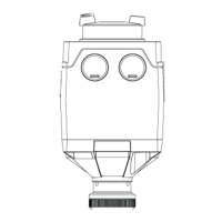
Provides dimensional drawings and data for stroke actuators with manual adjuster.
Gives dimensions for stroke actuators without a manual adjuster.
Shows dimensions for the external Modbus converter.
Lists product numbers and their valid revision numbers.
Explains common symbols used in the document.
Defines technical terms and abbreviations used in the manual.
Defines terms like PN, Position Feedback, and Forced Control.
| Brand | Siemens |
|---|---|
| Model | SAS61.03U |
| Category | Controller |
| Language | English |