Connecting up
5.1 Connectors for external antennas and power supply
SCALANCE W788-xPRO/RR / W74x-1PRO/RR
22 Operating Instructions, 07/2014, A5E02280448-08
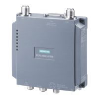
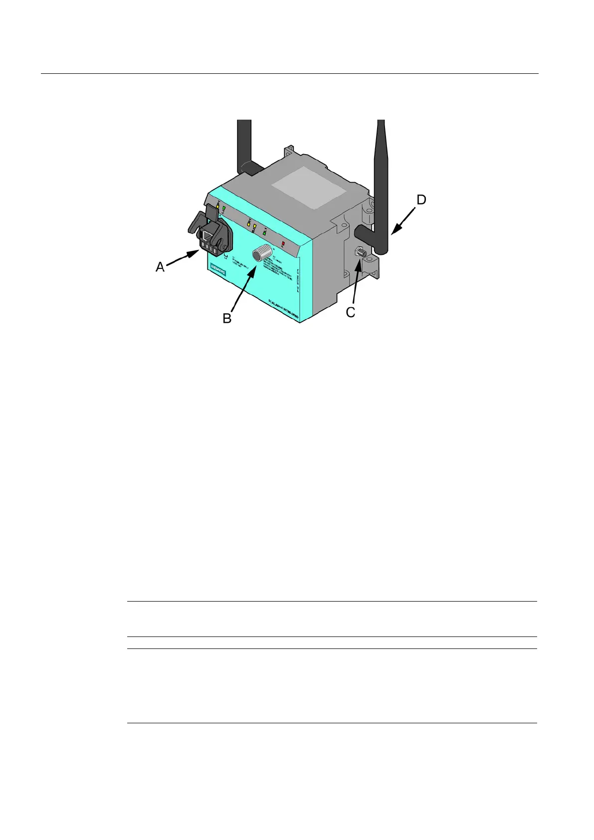
Figure 5-1 Connectors of the SCALANCE W788-xPRO/RR or W74x-1PRO/RR. The additional
antenna connectors (position C) only exist for the types W788-2PRO and W788-2RR.
As an alternative or in addition to this, you can also use the M12 plug for the power supply
(position
in the previous figure).
You can fit additional antennas to the sides of the SCALANCE W788- 2PRO and
SCALANCE W788-2RR with an antenna cable (position
in the previous figure). If you
install the SCALANCE W788-xPRO/RR or W74x-1PRO/RR in a cabinet, you will need to
unscrew the antennas due to the restricted communication (position
in the figure). In this
case, the connection is over detached antennas installed outside the cabinet. On the front
panel, there is also an identifier for the antenna connectors. The A connectors are on the
right-hand side and B connectors B on the left-hand side.
Suitable connecting cable for a connection between SCALANCE W788-xPRO/RR or W74x-
1PRO/RR and a detached antenna are available from SIMATIC NET. You will find detailed
information in the section "Suitable antenna cables and antennas for the SCALANCE W-
700".
Arrangement of interfaces and connectors
Note
The distance between the antennas of the various WLAN interfaces must be at least 1 m.
Note
Terminating resistor
Each WLAN interface has two antenna connectors. If you use only one connector, make
sure that you connect a terminating resistor to the sec
ond connector to ensure trouble-free
operation of the SCALANCE W788
-xPRO/RR or W74x-1PRO/RR.
 Loading...