Connection
5.3 Grounding
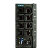
SCALANCE X-200
84 Compact Operating Instructions, 12/2010, A5E00813159-11
The connection or disconnection of a communication node on an unmonitored port does not
lead to an error message.
The signaling contact remains activated until the error/fault is eliminated or until the current
status is applied as the new desired status using the button.
When the IE Switch X-200 is turned off, the signaling contact is always activated (open).
5.3 Grounding
Installation on a DIN rail
The device is grounded over the DIN rail.
S7 standard rail
The device is grounded over its rear panel and the neck of the screw.
Wall mounting
The device is grounded by the securing screw in the unpainted hole.
Please note that X-200 IE switches must be grounded over one securing screw with
minimum resistance.
If an IE Switch X-200 is mounted on a non-conducting base, a grounding cable must be
installed. The grounding cable is not supplied with the device. Connect the paint-free surface
of the device to the nearest grounding point using the grounding cable.
 Loading...