Installation
5.2 Installing a switch
SCALANCE X-300
116 Operating Instructions, 02/2012, A5E01113043-12
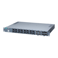
19" rack mounting
19" rack mounting is possible for all rack devices identified by (XR).
Refer to the technical specifications, Installation options table for each product group. The
rack device is installed using two mounting brackets fitted to the front. After fitting the two
mounting brackets, the rack device can then be installed in a 19" cabinet.
CAUTION
Do not cover the ventilation grilles
During installation, select a mounting position so that the ventilation grilles are always free
to achieve adequate cooling. In the standard position, the ventilation grilles are on the top,
bottom and sides of the housing.
If you install more than one rack device, make sure that the permitted ambient conditions
are met for all devices in the rack.
Minimum clearances
If you install the IE Switch in rack devices without forced ventilation or cooling, minimum
clearances must be maintained to neighboring devices or the wall of the enclosure. By
keeping to the minimum clearances, there is then an adequate stream of air for heat
dissipation during operation. Keep to the following minimum clearances to neighboring
devices.
Table 5- 4 Minimum clearances for installation in rack devices
Minimum clearance to devices below the switch 100 mm
Minimum clearance to devices above the switch 100 mm
CAUTION
Four-point mounting
If mechanical load is high, the device should be secured at four points. You will find more
detailed information in the section "Mechanical stability in operation".
 Loading...