Installation
5.2 Installing a switch
SCALANCE X-300
Operating Instructions, 02/2012, A5E01113043-12
117
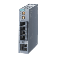
Standard position
Normal orientation of the device
• The ventilation grilles are on the top, bottom and sides of the
housing.
• The LED display is on the left of the front panel of the
housing.
• To the right of the LED display, the SCALANCE XR-300 has
connectors for the signaling contacts and the power supply.
Note that the SCALANCE XR-300 is available for different
power supplies (100 to 240 VAC and 24 VDC variants).
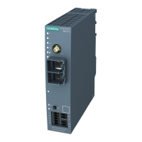
• The Ethernet ports or the slots for the modules are also on
the front of the housing. Slots for the modules are fitted with
dummy covers.
• The C-PLUG is on the right behind a protective panel
secured with screws.
(For more detailed information, refer to the section on the C-
PLUG in the X-300 operating instructions.)
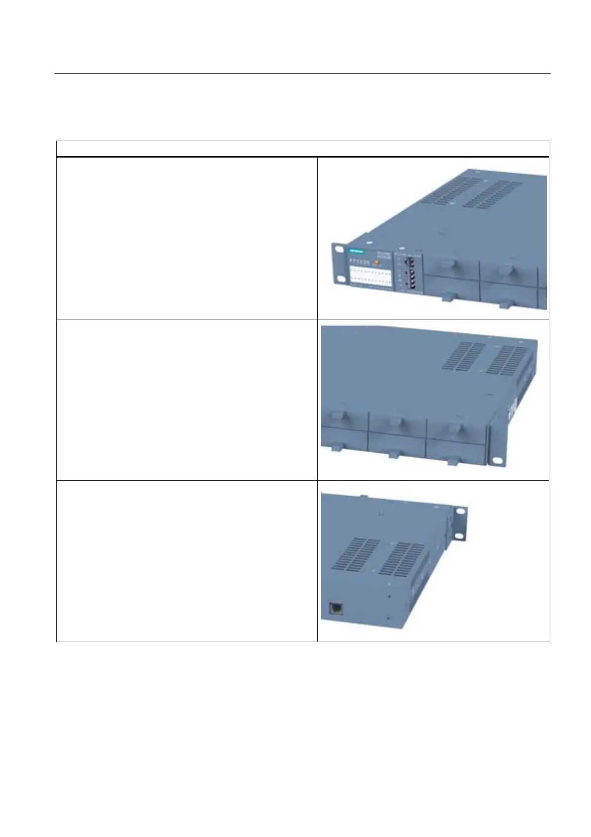
• On the back of the housing, you will find the diagnostics port
of the device. (For more details, refer to Diagnostics port
XR-300.) On the SCALANCE X-300M EEC, you will also
find the connectors for the signaling contacts and power
supply here.
 Loading...