3WL Air Circuit Breakers
9
Siemens · 2009
3WL Air Circuit Breakers/Non-Automatic Air Circuit Breakers up to 6300 A (AC)
General data
Main circuit connections – connection types
Main circuit connections
All circuit breakers are equipped with horizontal main circuit
connections on the rear for up to 5000 A as standard (horizontal
connection to busbars). Exception: Circuit breakers of size II
with max. rated current 4000 A.
Circuit breakers with a max. rated current of 6300 A and circuit
breakers size II with a max. rated current of 4000 A are equipped
with vertical main connections (for upright busbars).
The following options are available, with all combinations of top
and bottom connections possible:
• Accessible from the front, single hole (for vertically installed
busbars)
• Accessible from the front, double hole (holes according to
DIN 43673) (for vertically installed busbars)
• At the rear, vertical (for vertically installed busbars)
• Connecting flange (for direct connection to guide frame up to
4000 A).
Connection options for auxiliary circuit connections
Auxiliary circuit connections
The type of connection for the auxiliary switches depends on the
type of installation:
• Withdrawable version: The internal auxiliary switches are con-
nected to the male connector on the switch side. When fully in-
serted, the connector makes a connection with the sliding
contact module (see "Design", graphic "Guide Frame") in the
guide frame. Various adapters can then be used to complete
the wiring (see the graphic "Connection Options for Auxiliary
Circuit Connections").
• Fixed mounting: In this case the auxiliary supply connectors
are engaged directly onto the circuit breaker. The connectors
are equipped with coding pins that prevent them being mista-
kenly interchanged.
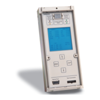
Operator panel
The operator panel is designed to protrude from a cut-out in the
door providing access to all control elements and displays with
the control cabinet door closed.
The operator panels for all circuit breakers (fixed-mounted/with-
drawable versions, 3-/4-pole) are identical. The operator panel
ensures degree of protection IP41.
Safety and reliability
To protect the circuit breakers and plant against unauthorized
switching as well as the maintenance and operator personnel, the
system contains many locking devices. Others can be retrofitted.
Other safety features include:
• Infeed from above or below, as required
• Locking of the guide frame with the circuit breaker removed,
as standard
• Locking of the withdrawable circuit breaker against move-
ment, as standard
• High degree of protection with cover IP55
• Mechanical reclosing lockout after overload or short-circuit
release as standard
• The circuit breaker is always equipped with the required num-
ber of auxiliary supply connectors
Standard version
SENTRON 3WL circuit breakers are equipped with the following
features as standard:
• Mechanical ON and OFF pushbutton
• Manual operating mechanism with mechanical closing
• Switch position indicator
• Ready-to-close indicator
• Memory status indicator
• Auxiliary switch 2 NO + 2 NC
• Rear horizontal main circuit connections for fixed-mounted and
withdrawable versions up to 5000 A, and rear vertical main cir-
cuit connections for 6300 A applications and size II with 4000 A
• For 4-pole circuit breakers, the fourth pole (N) is installed on
the left and is 100 % loadable with the rated current
• Contact erosion indicator for the main contacts
• Auxiliary circuit plug-in system with SIGUT screw terminals
Delivery inclusive of all auxiliary circuit connectors to internal
features including coding device for the prevention of incor-
rect installation of auxiliary supply connectors for fixed-moun-
ted circuit breakers
• Mechanical "tripped" indicator for solid-state release system
• Mechanical reclosing lockout after tripping operation
• Operator panel cannot be taken off with the circuit breaker in
the ON position
Additional features of the withdrawable version:
• Main contacts:
Laminated receptacles in the guide frame, penetration blades
on the withdrawable circuit breaker
• Position indicator in the operator panel of the withdrawable
circuit breaker
• Captive manual crank handle for moving the withdrawable
circuit breaker
• Guide frame with guide rails for easy moving of the withdra-
wable circuit breaker
• The withdrawable circuit breaker can be locked to prevent it
being pushed out of position
• The withdrawable circuit breaker cannot be moved when it is
in the ON position
• Coding of the rated current between the guide frame and the
withdrawable circuit breaker
Standards
SENTRON 3WL circuit breakers comply with:
• IEC 60947-1, IEC 60947-2
• EN 60947-1, EN 60947-2
• Climate-proof according to IEC 60068-2-30
Versions according to UL 489 also available, see Catalog LV 16.
For further specifications, see Appendix.
Horizontal
connection
Front connection with single
hole or double hole
Vertical
connection
Horizontal
connection
Front connection with single
hole or double hole
Vertical
connection
Flange
connection
Fixed-mounted circuit breakers
Withdrawable circuit breakers and guide frames
Connection using
screw terminals
system (SIGUT)
(standard)
Screwless
connection method
(tension springs)
(optional)

 Loading...


