4
L1V30560078-01
3ZW1012-0WL00-3AA0
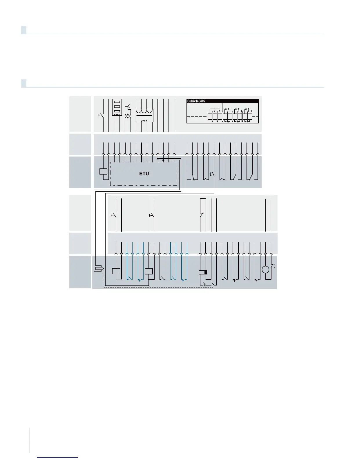
The electronic trip unit must be supplied with a voltage of 24 V DC. To this end, +24 V DC (positive) must be applied at the X8.3 auxiliary connector
and -24 V DC (negative) at X8.4. The same 24 V DC are connected inside the breaker with option Z=K60 and Z=K62 to the internal relay.
The voltage of 24V … 230V (depending on the selected undervoltage release) for supplying the undervoltage release is connected at X5.11 and X5.12
- see wiring diagram below.
Connection
Circuit diagram of auxiliary current connections with option Z=K60
Interne
Beschaltung
Internal
wiring
Klemmen
Terminals
Externe
Beschaltung
External
wiring
14
13
12 11
10 9 8 7 6
5
4
3
2114
13
12 11
10 9 8 7 6
5
4
3
21
X7X8
123456789
Write
Enable
Fr
ee
Fr
ee C
l
ose O
p
e
n
+
–
+
–
+
–
IN OUT
External
Internal
Y1
F1, 2
Externe
Beschaltung
Interne
Beschaltung
Internal
wiring
Klemmen
Terminals
14
13
12 11
10 9 8 7 6
5
4
3
21 14
13
12 11
10 9 8 7 6
5
4
3
21
M
X6 X5
BK BN
External
wiring

 Loading...


