Maximum permissible gain: Antenna and additional attenuation elements
When using antennas with a very high antenna gain, the maximum permitted EIRP (equivalent
isotropic radiated power) of the device is often exceeded even at minimum transmit power.
Additional attenuation elements must therefore be used between the device and the antennas.
The "Max. permitted gain" column in the table above shows the maximum permitted antenna
gain (total value) that can be connected to the antenna sockets of the devices. If the typical
antenna gain of the antennas to be connected exceeds the maximum permissible value, you
must compensate for the dierence by using attenuation elements, for example, an attenuator
or connecting cables.
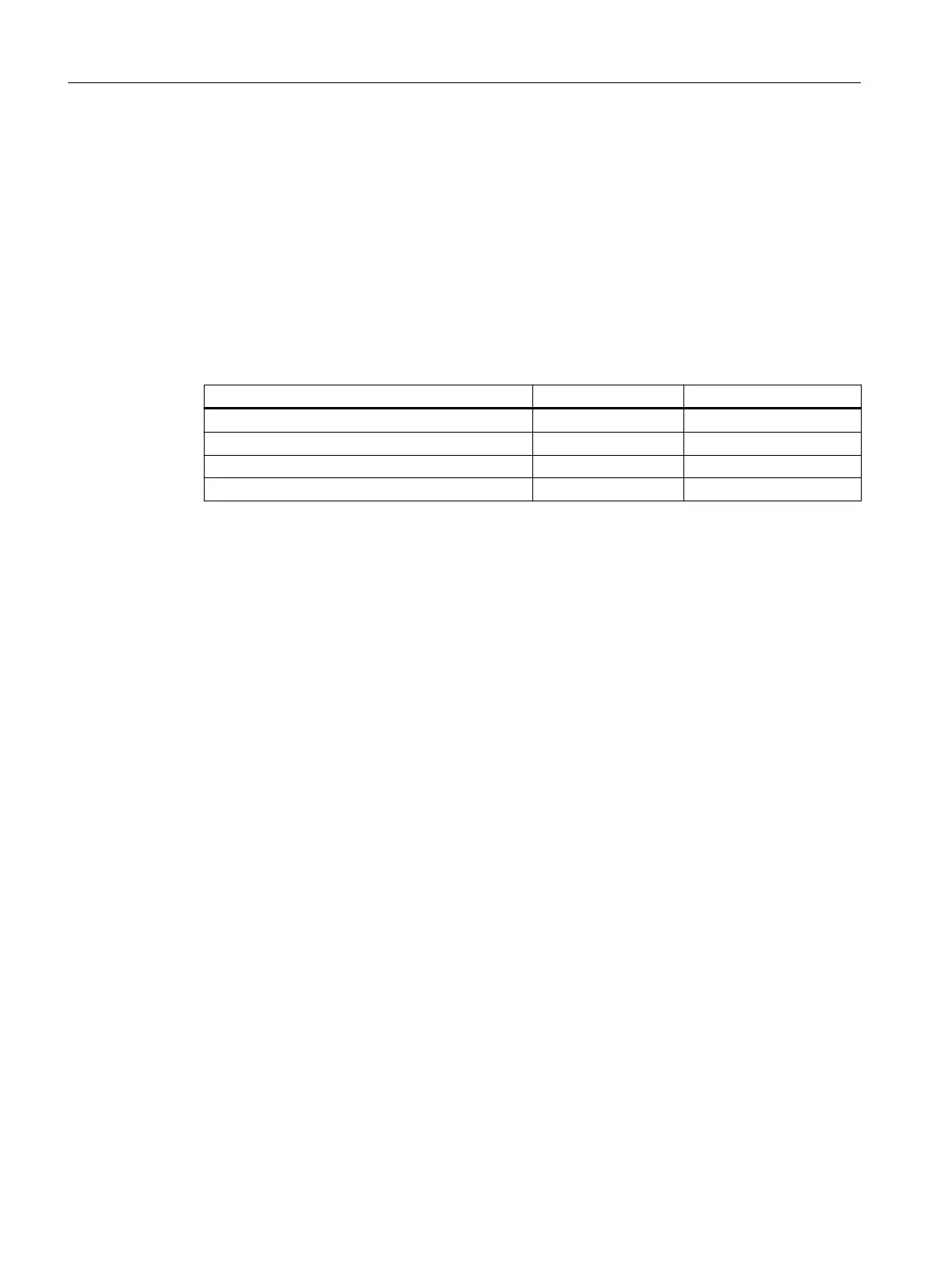
The following table provides an overview of possible attenuation elements and their
attenuation values:
Name Attenuation Article number
Attenuator 10dB 6GK5798-0AP00-4CA0
Antenna connecting cable, 1m long 1.0dB 6XV1875-5xH10
Antenna connecting cable, 2m long 1.8dB 6XV1875-5xH20
Antenna connecting cable, 5m long 4.3dB 6XV1875-5xH50
Example
The antenna ANT793-8DL is used.
• Typical antenna gain: 14dBi
• Maximum permissible gain for channel 36 in Germany: 11dBi
In this case the typical antenna gain exceeds the maximum permissible gain by 3dBi. This
means you must use an attenuation element with at least 3dB. This can be a connecting
cable, for example, with a length of 5 meters.
SCALANCE WxM766-1
1.6National approvals
Approvals SCALANCE W700 802.11ax
34 Reference Manual, 04/2023, C79000-G8976-C621-05

 Loading...


