Do you have a question about the Siemens SIMATIC S7-1500 CPU 1511-1 PN and is the answer not in the manual?
Explains the grading of safety alert symbols and warnings for personal injury and property damage.
Defines who is qualified to operate the product safely based on training and experience.
Notes on correct usage, including warnings and recommendations for safe operation.
Lists registered and third-party trademarks used in the publication.
States the publisher's responsibility regarding content accuracy and potential variances.
Explains the manual's role in supplementing system and function manuals for commissioning the CPU.
Defines terms like "STEP 7" and notes usage conventions for the documentation.
Provides instructions for environmentally friendly recycling and disposal of old equipment.
Information about Siemens' online catalog and order system for automation solutions.
Describes the arrangement of documentation into three areas for accessing specific content.
Details System Manual and Getting Started for configuration, installation, and commissioning.
Explains equipment manuals cover module-specific details like properties and diagrams.
Describes function manuals covering general topics for SIMATIC S7-1500/ET 200MP systems.
Explains Product Information documents for changes and supplements to manuals, taking precedence.
Information about the combined documentation file for S7-1500/ET 200MP systems.
Lists instructions and functions usable across different controller families.
Points to additional SIMATIC documents and industry online support for further information.
Guides users to find SIMATIC documentation in Siemens Industry Online Support via links and videos.
Explains how to use mySupport for registration, support requests, favorites, and CAx data.
Describes how application examples help solve automation tasks with tools and solutions shown in system interplay.
Discusses Siemens' industrial security functions, cyber threat protection, and customer responsibilities.
Overviews the most important new firmware functions of the CPU compared to the predecessor version.
Introduces SIMATIC S7-1500 as a modular control system for discrete automation applications.
Lists advantages and application areas for S7-1500, S7-1500R/H, and S7-1500T systems.
Details performance segments, interfaces, and memory for various standard S7-1500 CPUs.
Describes performance segments of redundant S7-1500R/H CPUs for reliability and availability.
Outlines performance segments, integrated I/O, and technology functions for compact CPUs.
Details performance of technology CPUs used primarily for drive control.
Explains fail-safe CPUs for demanding standard and safety applications.
Discusses password protection, copy protection, access rights, and manipulation protection for CPUs.
Describes the CPU display, plain text information, modular design, and ease of expansion.
Explains integrated system diagnostics and alarm display on CPU, STEP 7, HMI, and Web server.
Lists the article number and basic hardware properties of the CPU.
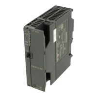
Shows a front view image of the CPU 1511-1 PN with numbered components.
Details CPU display features, network settings, error message display, and links to simulator.
Specifies the 24 V DC supply voltage connection via a 4-pin plug at the bottom.
Describes the PROFINET interface X1 with two ports, supporting RT and IRT modes.
Directs users to the system manual for information on accessories and spare parts.
Lists supported firmware functions including integrated system diagnostics and web server.
Explains trace functionality for troubleshooting and program optimization via device tags.
Details OPC UA for manufacturer-neutral data exchange as client and server.
Explains using configuration control for operating different hardware configurations with one project.
Details RT (real time) protocol for prioritizing PROFINET IO telegrams.
Explains IRT for time-synchronized intervals and maximum determinism.
Describes Isochronous mode for high control quality, precision, and reduced reaction times.
Explains establishing redundant networks via Media Redundancy Protocol for alternative communication paths.
Describes MRPD for uninterrupted IO data supply during ring failures with short update times.
Explains dividing IO modules or submodules among different IO controllers for flexible automation.
Details PROFlenergy for central consumer switching off during pause times to save energy.
Introduces technology objects for controlled positioning and axis travel in motion control.
Lists technology objects for motion control like speed-controlled, positioning, and synchronous axes.
Details PID controllers (Compact, 3Step, Temp) with integrated optimization features.
Mentions integrated safety functions available in SINAMICS drives.
Explains know-how protection for user blocks against unauthorized access and modifications.
Describes copy protection linking user blocks to memory card/CPU serial numbers.
Explains assigning authorization levels to different users for access control.
Details integrity protection to detect manipulation of engineering data.
Describes connecting a password provider to STEP 7 for convenient password handling.
Introduces the operating and display elements of the CPU, including LEDs and buttons.
Shows and describes the front view of the CPU, including its display and operator control buttons.
Provides instructions and warnings for safely removing/fitting the front panel or display.
Explains how to lock the front panel using a security seal or padlock for access protection.
Directs users to the system manual and simulator for detailed display options and menu commands.
Shows operator controls and connection elements on the front of the CPU without the panel.
Shows the connection elements on the back of the CPU 1511-1 PN, including memory card slot and interfaces.
Explains the meaning and operation of the CPU's operating mode buttons (RUN, STOP, MRES).
Details the pin assignment for the 24 V DC supply voltage connector and loop-through functionality.
Describes the PROFINET interface assignment, ports, autonegotiation, and switch allocation.
Directs users to the system manual for information on removing and replacing the display.
Points to the system manual for topics on connecting the CPU and accessories.
Explains the CPU has three MAC addresses for its PROFINET interfaces and their purpose.
Shows the block diagram of the CPU 1511-1 PN, illustrating its main components and connections.
Describes the LED display of the CPU for current operating mode and diagnostics status.
Explains the meaning of various combinations of colors for the RUN/STOP, ERROR, and MAINT LEDs.
Details the various LED scenarios for the LINK RX/TX LEDs on PROFINET ports indicating connection status.
Explains the meaning of the STOP ACTIVE LED and its behavior when the CPU is in STOP mode.
Lists product type designation, HW functional status, and firmware version of the CPU.
Details product functions like I&M data support and isochronous mode capabilities.
Specifies the STEP 7 TIA Portal version required for configurable/integrated engineering.
Explains the use of configuration control via dataset for managing hardware configurations.
Provides the screen diagonal measurement in centimeters.
Lists the number of keys and mode buttons on the CPU.
Specifies rated, permissible lower, and upper limits for DC supply voltage.
Details mains/voltage failure stored energy time and minimum repeat rate.
Lists rated current consumption, maximum current, and inrush current.
Specifies the power infeed to the backplane bus.
Specifies the power consumption from the backplane bus when balanced.
Details the typical power loss of the CPU.
Lists the number of slots for SIMATIC memory card and if a card is required.
Details integrated memory for program and data storage.
Specifies the maximum capacity of a plug-in SIMATIC Memory Card.
Notes if the backup function is maintenance-free.
Lists processing times for bit, word, fixed point, and floating point operations.
Details number range and max size for DB, FB, FC, and OB blocks.
Specifies the nesting depth per priority class for interrupts.
Details S7 and IEC counters/timers and their retentivity settings.
Specifies retentive data area and extended retentive data area size.
Lists maximum size for flags and number of clock memories.
Details retentivity adjustability and preset for data blocks.
Refers to the system manual for specifications on local data.
Specifies the address area for IO modules and per integrated IO subsystem (inputs/outputs).
Details the maximum number of subprocess images supported.
Covers distributed IO systems, DP masters, IO controllers, and racks.
Specifies the number of connectable PtP CMs based on available slots.
Details clock type, backup time, and maximum daily deviation.
Specifies the number of operating hours counters.
Notes if clock synchronization is supported.
Lists update times for various send cycles in IRT mode, noting isochronous OB impact.
Lists update times for various send cycles in RT mode.
Details PROFINET IO Device services like PG/OP communication, IRT, and PROFlenergy.
Describes the RJ45 Ethernet interface, number of ports, and integrated switch functionality.
Lists supported protocols including PROFIsafe.
Specifies the maximum number of connections via integrated interfaces and CPs/CMs.
Details H-Sync forwarding and Media redundancy (MRP, MRPD) modes.
Covers PG/OP communication, S7 routing, data record routing, and S7 communication as server/client.
Lists various open IE communication protocols like TCP/IP, ISO-on-TCP, UDP, DHCP, DNS, SNMP, DCP, and Encryption.
Specifies the capabilities of the Web server for HTTP and HTTPS access.
Details OPC UA Client and Server functionalities, security policies, user authentication, and connection limits.
Lists additional protocols supported, such as MODBUS.
Covers login stations, program alarms, and loadable program messages.
Details joint commission, status block, single step, and breakpoint capabilities.
Specifies status/control variables and their maximum limits per job.
Details forcing capabilities for peripheral inputs/outputs and their variable limits.
Covers diagnostic buffer entries, maximum entries, and powerfail-proof entries.
Specifies the number of configurable traces and the data storage capacity per trace.
Lists the diagnostics indication LEDs (RUN/STOP, ERROR, MAINT, STOP ACTIVE, LINK TX/RX).
Lists Motion Control resources and required resources per axis type.
Details PID controllers (Compact, 3Step, Temp) with integrated optimization features.
Mentions the availability of a high-speed counter.
States if the product is suitable for safety functions.
Specifies ambient temperature ranges for operation and storage/transportation.
Specifies the maximum installation altitude above sea level.
Lists the supported programming languages (LAD, FBD, STL, SCL, GRAPH).
Details user program protection, copy protection, and block protection features.
Mentions various access protection features for data and configuration.
Specifies the adjustable limits for minimum and maximum cycle time monitoring.
Lists the width, height, and depth of the CPU module.
Provides the approximate weight of the CPU module.
Refers users to the system manual for general specifications like standards and EMC.
Includes dimensional drawings of the CPU on a mounting rail and with the front panel open.
| Firmware Version | V2.0 or higher |
|---|---|
| Supply Voltage | 24 V DC |
| Program Memory | 150 KB |
| Data Memory | 1 MB |
| Bit Performance | 60 ns |
| Number of PROFINET Ports | 2 |
| Web Server | Yes |
| Integrated Display | No |
| Number of Connections | 64 |
| Processor Type | SIMATIC S7-1500 |
| Engineering with | STEP 7 Professional V13 or higher |
| Input Current | 0.8 A |
| Number of Slots | 32 |
| Communication | PROFINET |
| Integrated Interfaces | PROFINET |
| Operating Temperature | 0 °C to 60 °C |
| Dimensions | 35 x 147 x 129 mm |
| Weight | 430 g |