3.5.2 Front view of the CPU without front panel and view from below
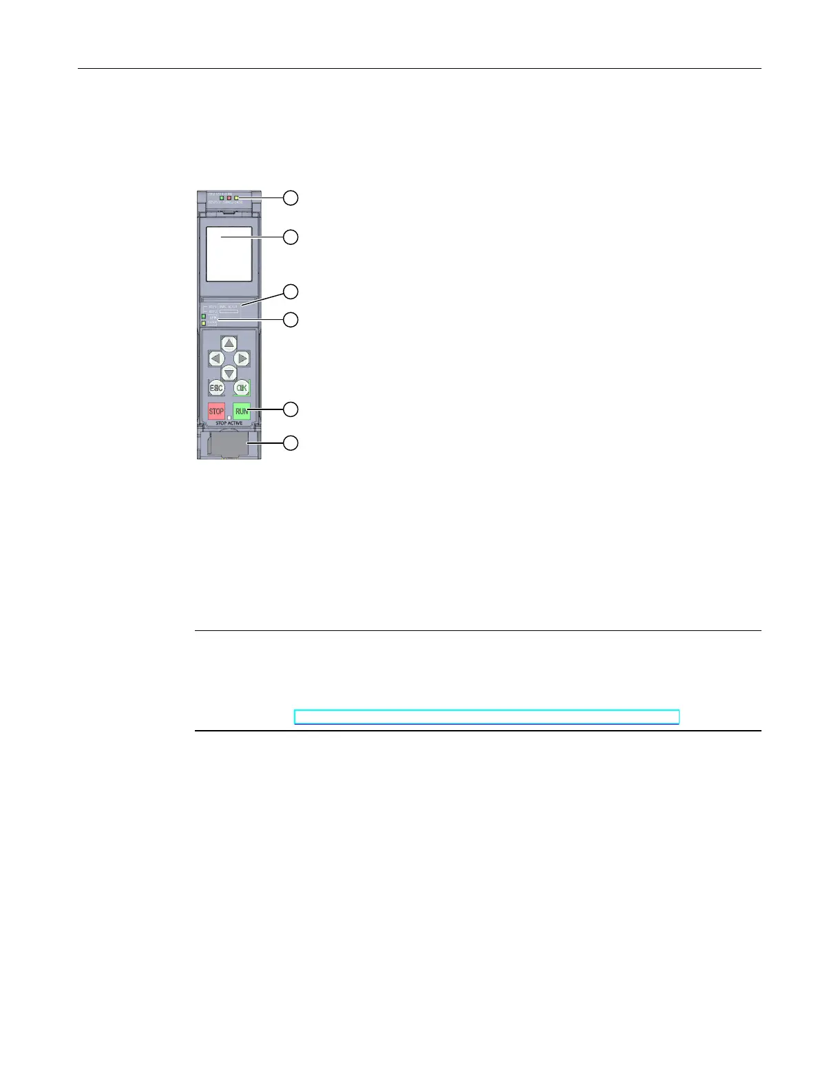
The following figure shows the operator controls and connection elements of the
CPU1511-1PN.
① LEDs for the current operating mode and diagnostic status of the CPU
② Display
③ MAC address
④ LED displays for the 2 ports of the PROFINET interface X1
⑤ Operating modes with "STOP ACTIVE" LED
⑥ Connector for power supply
Figure 3-4View of the CPU1511-1PN (without front panel) – front
NOTE
Removing the display
Only remove the display if it is faulty.
You can find information on removing and replacing displays in the S7‑1500, ET200MP
system manual (https://support.industry.siemens.com/cs/ww/en/view/59191792).
27
Product overview
3.5 Operating and display elements
CPU 1511-1 PN (6ES7511-1AL03-0AB0)
Equipment Manual, 11/2022, A5E40869673-AC

 Loading...


