Siemens PLT 112 · 2002
6/3
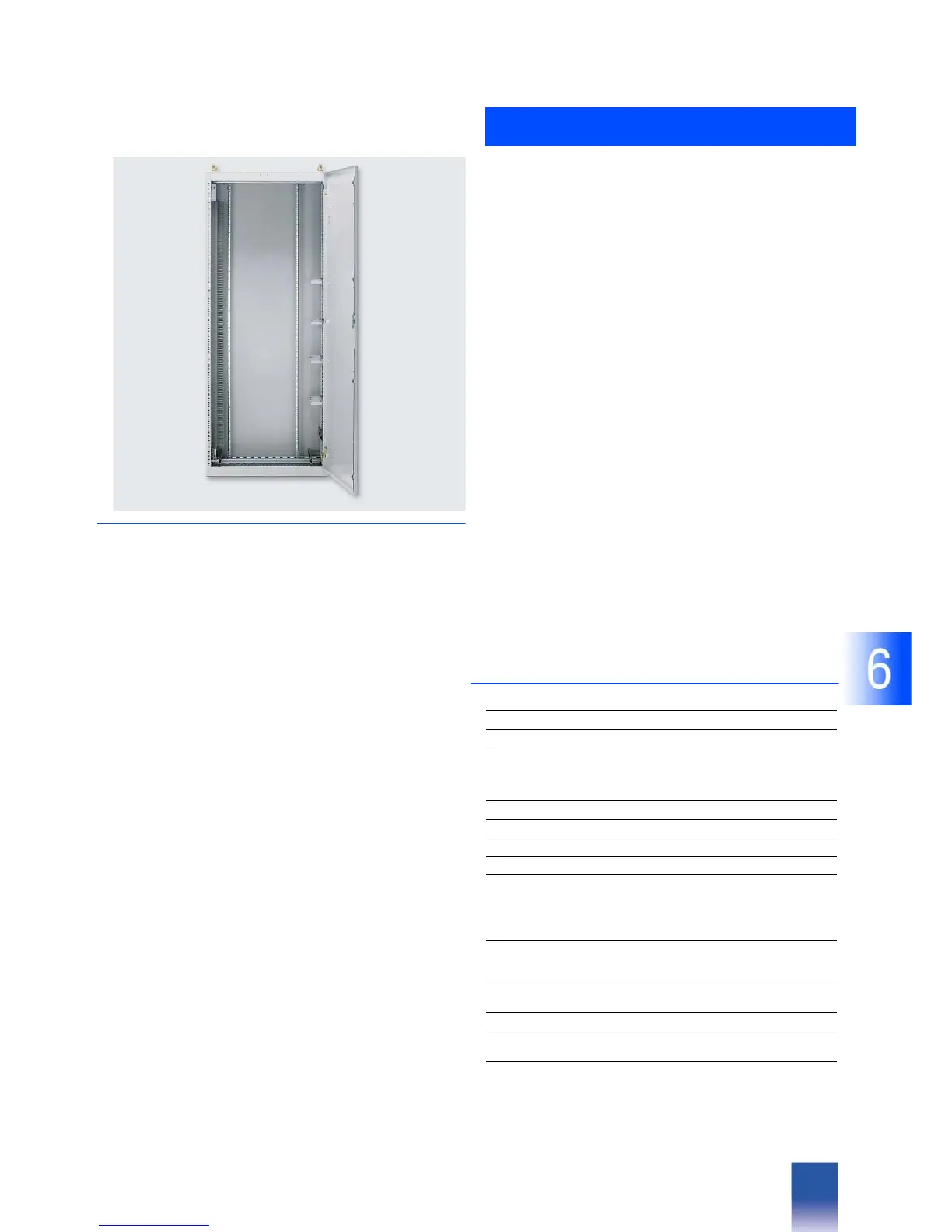
SIMATIC PCS 7 cabinet design
Basic cabinet
■
Overview
The Siemens standard cabinet 8MC is the preferred basic cabi-
net. The Siemens standard cabinet 8MC is a sheet-steel cabinet
with rear panel and front door which can be assembled individ-
ually or also in rows with further cabinets of this type.
Side walls and partitions are optional, thus permitting variable
adaptation of the cabinet to different installation possibilities.
Up to four system units or six I/O units can be fitted in a cabinet
in conjunction with a DC 24 V or AC 230 V power supply assem-
bly. System and I/O units can also be combined together within
a cabinet. The cables are introduced into the cabinet from be-
low.
Mechanical design
Each delivered cabinet contains:
• 19-inch mounting frame
• Rear panel
• Door
•Transport lugs
• Clips for routing of process cables
• Cable duct for cabinet-internal wiring
Options for the mechanical design
When ordering the basic cabinet, the following options are avail-
able for the mechanical design of the cabinet:
• Plinth: a cabinet plinth should be used if cables cannot be con-
nected through the floor. The plinths are preassembled, and
available with a height of 100 or 200 mm
• Pocket for documents
•Trim
• Side walls/partitions: the basic cabinets are suitable for individ-
ual assembly or in rows. Therefore side walls and/or partitions
can be selected when ordering.
Electrical design
Each delivered cabinet contains:
• Power supply assembly AC 230 V or DC 24 V
• Cable clamps and screen bars for I/O and bus cables
• Prewiring of power supply cables for central and I/O units
• Wiring of PROFIBUS-DP fieldbus
• Connector board for cabinet earth
Options for the electrical design
• AC 230 V socket (installed in power supply assembly)
• I & C monitoring (2 versions):
- I & C monitoring via cabinet lamp. A blown fuse is signalled
by a lamp in the cabinet door. OLM failure can be additionally
displayed on the cabinet lamp
or
- I & C monitoring via AS 488/TM and cabinet lamp. Tempera-
ture violations in the cabinet, an open door contact, a blown
fuse and an OLM failure can be recorded by the IF 961-DIO
interface module and additionally signalled by a lamp in the
cabinet door
- Single/redundant design of power supply assembly, option-
ally with 6 or 14 circuit-breaker receptacles
• Cabinet illumination
Preparation of quotation, consulting and ordering
Siemens AG
D-76187 Karlsruhe
Tel.: +49 721 595-3776
Fax: +49 721 595-4711
E-mail: helmut.heib@siemens.com
■
Technical Specifications
Siemens standard cabinet
Dimensions (H x W x D) in mm 2000 x 800 x 400
Framework, completely welded Sheet-steel, 2 mm,
frame profile with 10 edges,
cross-member profile with 5
edges
Rear panel Sheet-steel, 1.5 mm, canted
Roof Sheet-steel, 1.5 mm, canted
Side wall (option) Sheet-steel, 1.5 mm, canted
Partition (option) Sheet-steel, 1.5 mm, canted
Single-leaf door on front of cabinet
with hinge on right
Sheet-steel, 1.5 mm,
opening angle approx. 180°;
including rod lock with 3 mm lock
insert and double-barb key
DIN 43 668
Degree of protection to EN 60 529 IP 40, with single installation or
together with cabinets of the
same type
Color Ergo gray to
SN 30 920-C611-B13
Permissible ambient temperature Max. 40 °C
Permissible temperature inside
cabinet
Max. 55 °C
Permissible heat dissipation with-
out fan
350 W, referred to maximum val-
ues of ambient temperature and
temperature inside cabinet
 Loading...


