Connection
5.5 Connecting the communications module
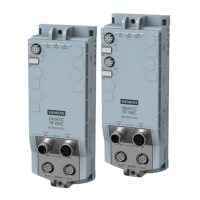
SIMATIC RF185C, RF186C, RF188C, RF186CI, RF188CI
Operating Instructions, 04/2020, C79000-G8976-C512-03
43
Table 5- 4 Pin assignment reader interface; M12 socket (8-pin, A-coded)
View of M12 socket, 8-pin
5 +TxD +5 V
8 Functional ground
/ shielding
Functional ground
/ shielding
I/O interface (RF18xCI)
Note that a single input, a single output or an IO-Link module (e.g. IO-Link module K20) can
be connected to the I/O interface.
Table 5- 5 Pin assignment I/O interface; M12 socket (5-pin, A-coded)
View of M12 socket, 5-pin
2 2L+: +24 V, for IO-Link module
4 C/Q: Data cable for
• IO-Link
• a single digital input
• a single digital output
5 2N: GND, for IO-Link module