Do you have a question about the Siemens SIMATIC RF188C and is the answer not in the manual?
Guidelines for creating strong passwords and managing user accounts for security.
Information on using SSL certificates for secure communication and supported formats.
Explains how to mount the modules on a flat surface or aluminum profile.
Provides information on connecting the modules to PROFINET IO and safety precautions.
Details overall configuration on grounded/ungrounded power supply, including voltage.
Highlights protection measures against electrical impacts and faults.
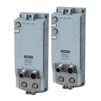
Illustrates the communication module design and lists interface connectors.
Shows pin assignments for PROFINET IO and power supply connectors.
Details pin assignments for reader interfaces (RS422/RS232).
Wiring notes regarding cable length effect on voltage and current carrying capacity.
Explains assigning unique IP addresses or device names for functioning communication.
Step-by-step guide for assigning device names using TIA Portal and PROFINET.
Step-by-step guide for assigning IP addresses and device names using SINEC PNI.
Describes assigning IP addresses via DHCP, primarily for Rockwell users.
Prerequisites for configuring the module via PROFINET IO using TIA Portal.
Explains setting basic parameters and reader parameters via the module's properties window.
Describes how to start Web Based Management for module configuration.
Details loading or saving configuration data within the STEP 7 project.
Allows configuration of all module-specific parameters of the communication module.
Enables configuration of module-specific parameters for connected readers.
Configures parameters specific to the "Freeport" submodule.
Describes how to start Web Based Management using a web browser.
Explains using WBM to configure SIMATIC RF18xC/RF18xCI communication modules.
Details the different areas of the WBM start window (toolbar, menu tree, main window, etc.).
Explains the buttons and information available in the WBM toolbar and status bar.
Provides an overview of the WBM menu items and their corresponding functions.
Allows defining up to four readers and their basic settings or reader parameters.
Allows setting digital output properties and assigning functions, specific to RF186CI/RF188CI.
Enables/disables network ports, SNMP, NTP, and Syslog messages.
Configures security profiles, methods, and allows anonymous access for OPC UA interface.
Displays status parameters of the selected reader and transponder in the antenna field.
Allows reading out and writing transponder data, divided into basic settings and read/write areas.
Enables reading/writing memory areas and accessing pre-defined addresses (tag fields).
Enables and manages user accounts, profiles, and passwords for secure access.
Covers user profiles, properties, passwords, roles, and enabling/disabling user management.
Manages firmware updates, resets, IP addresses, certificates, and device description files.
Updates the firmware of connected readers.
Details methods and functions supported by OPC UA servers for RFID devices.
Lists OPC UA server functions according to Micro Embedded Device Server Profile and AutoID specification.
Outlines RFID-specific methods like Scan, ReadTag, WriteTag supported for each read point.
Explains how OPC UA variables are used for querying information and making settings.
Lists available diagnostic options via LED displays, SNMP, WBM, TIA Portal, XML, and OPC UA.
Details the LEDs on the RF18xC/RF18xCI module for status, reader, I/O, and PROFINET/Ethernet diagnostics.
Explains the operating states shown by the RUN, ERROR, and MAINT LEDs.
Describes the states shown by the PRE and ER LEDs for reader status.
Lists supported MIBs for comprehensive network diagnostics via SNMP.
Explains various diagnostic options available through the WBM, including logs.
Guides S7 users on reading diagnostics information of modules and readers via TIA Portal.
Steps to read diagnostics information of readers connected to the module via TIA Portal.
Selects which diagnostic interrupt messages to view and how to deactivate them.
Lists error codes, flashing patterns, and causes for communication module errors.
Lists error codes, flashing patterns, and causes for communication module errors.
Describes errors related to field disturbance, interference, and too many transmit errors.
Covers errors related to low power supply and connection problems with the reader.
Details errors related to Ident profile/communication module communication and backplane bus/PROFIBUS errors.
Lists errors related to data block length, command codes, and acknowledgment frames.
Covers invalid parameter values in XML commands and presence errors.
Lists errors related to invalid parameter types, unknown parameters, and incorrect command formats.
Explains how to read out diagnostic messages from the WBM log.
Lists error descriptions related to firmware updates and configuration transfers.
Step-by-step guide for updating firmware using the Web Based Management interface.
Instructions for S7 users to update firmware via TIA Portal using Web Diagnostics.
Instructions for S7 users to update firmware of RF200 and RF300 readers via TIA Portal.
Details the process of browsing for update files and starting the firmware upgrade.
Steps to reset the communication module to factory settings using WBM.
Steps to reset the communication module to factory settings using WBM.
Instructions for resetting the reader to factory settings using SINEC PNI.
Manual procedure to restore factory settings by connecting pins 4 and 7 of the reader interface.
Emphasizes saving module configuration before replacement for transfer to the new module.
Emphasizes saving module configuration before replacement for transfer to the new module.
Notes on transferring user profiles and passwords, and enabling user management after loading config.
Describes methods for backing up configuration data (on controller, STEP 7 project, or PC).
Details saving module configuration into a STEP 7 project via TIA Portal.
Explains using WBM buttons to save, load, and transfer configurations to/from the PC.
Step-by-step guide for replacing a communication module, including IP/device name assignment.
Details technical specifications for RF185C, RF186C, and RF188C modules, including Ethernet and reader interfaces.
Details technical specifications for RF186CI and RF188CI modules, including Ethernet, reader, and I/O interfaces.
| Brand | Siemens |
|---|---|
| Model | SIMATIC RF188C |
| Category | Rfid Systems |
| Language | English |