Technical data
6.2 Technical data the RS 485 Repeater
RS 485 Repeater
Manual, 02/2011, A5E03382072-01
37
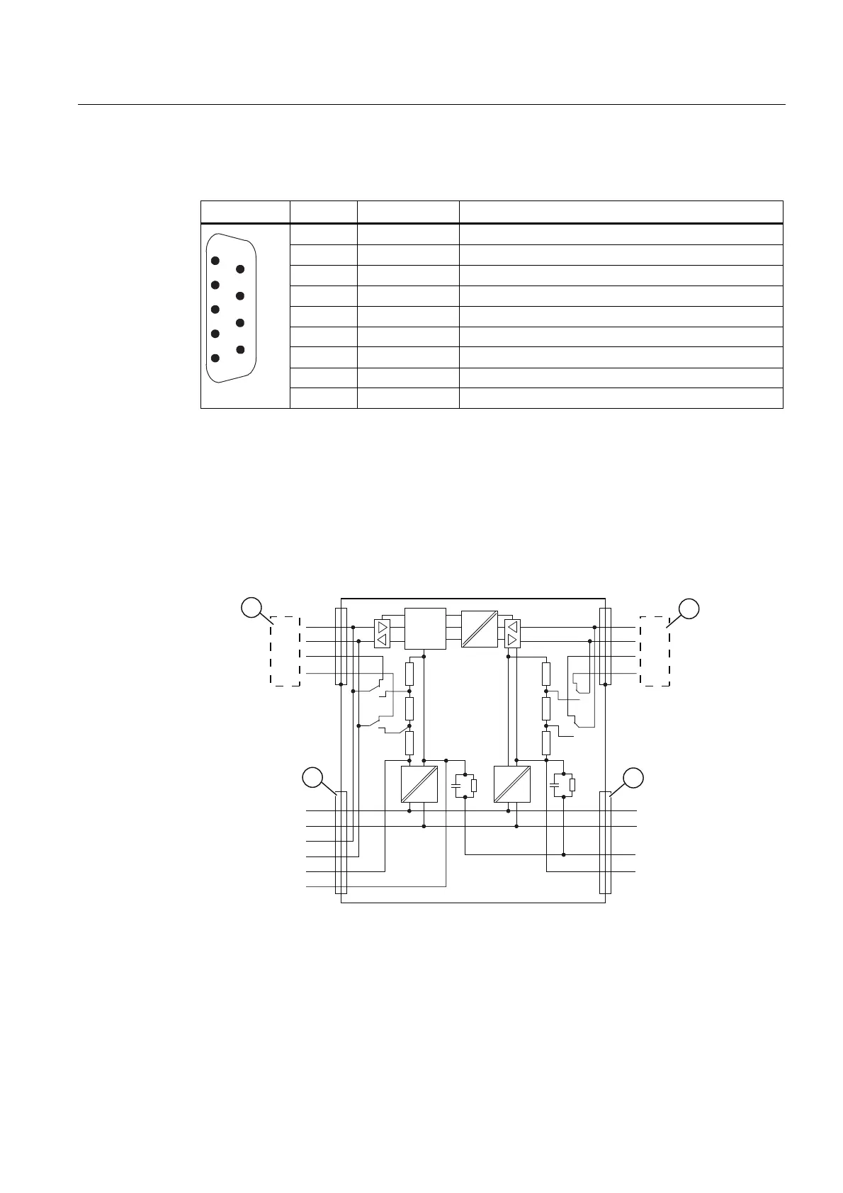
Pin assignment of the sub-D connector (PG/OP socket)
View Pin no. Signal name Designation
1 - -
2 M24V Ground 24 V
3 RxD/TxD-P Data line B
4 RTS Request To Send
5 M5V2 Data reference potential (from station)
6 P5V2 Supply plus (from station)
7 P24V 24 V
8 RxD/TxD-N Data line A
9 - -
Block diagram of the RS 485 Repeater
● Bus segments 1 and 2 are electrically isolated.
● Bus segment 2 and the PG/OP socket are electrically isolated.
● Signals are amplified
– between bus segments 1 and 2
– between PG/OP socket and bus segment 2
3
$
%
$
%
$
%
$
%
2))
21
2))
21
00
/9
0
3(
0
/9
0
$
%
9
9
9
9
9
09
/RJLN
① Bus segment 1
② Bus segment 2
③ PG/OP socket
④ PG/OP socket