5.0 - INSTALLATION
5.1
-INSTALLING
THE
GEAR UNIT
I.\
The entire installation process must be planned as early as the general design phase
of
the ma-
~
chine. The person authorised to do the
work
must,
if
necessary, set out a safety plan to protect
• the health and safety
of
all persons directly involved and apply all applicable legislation.
1.
Carefully remove all packaging and protective produet residue from the gear unit.
Pay particular attention to the mating surfaces.
2.
Check that the data
on
the nameplate correspond to those specified in the purehase arder.
3.
Ensure that the structure to which the gear unit is to be mounted is sufficiently robust and rigid to support
its weight and operating stresses.
4. Check that the machine to which the gear unit is to be installed is switched off and cannot be accidentally
switched
on
again.
5.
Make sure all mating surfaces are flat.
6.
Make sure the shafUshaft or shafU bore are perfectly aligned for coupling.
7.
Fit suitable guards
to
protect against the gear unit's external moving parts.
8.
lf
the work environment is corrosive for the gear unit or any of its parts, follow the special precautions re-
quired for aggressive environments.
In
this case, contact the BONFIGLIOLI TRASMITAL sales service.
9.
We recommend applying a protective paste to all gear unit/motor mating surfaces and other parts
(Kluberpaste 46 MR
401
or other produet with similar properties and application range) to ensure optimal
coupling and protection against fretting corrosion.
10.
In
the case of outdoor installations fitted with
an
electric motor, protect the latter from direct sunlight and
the weather by means of guards or a casing. Also make sure that the assembly is properly ventilated.
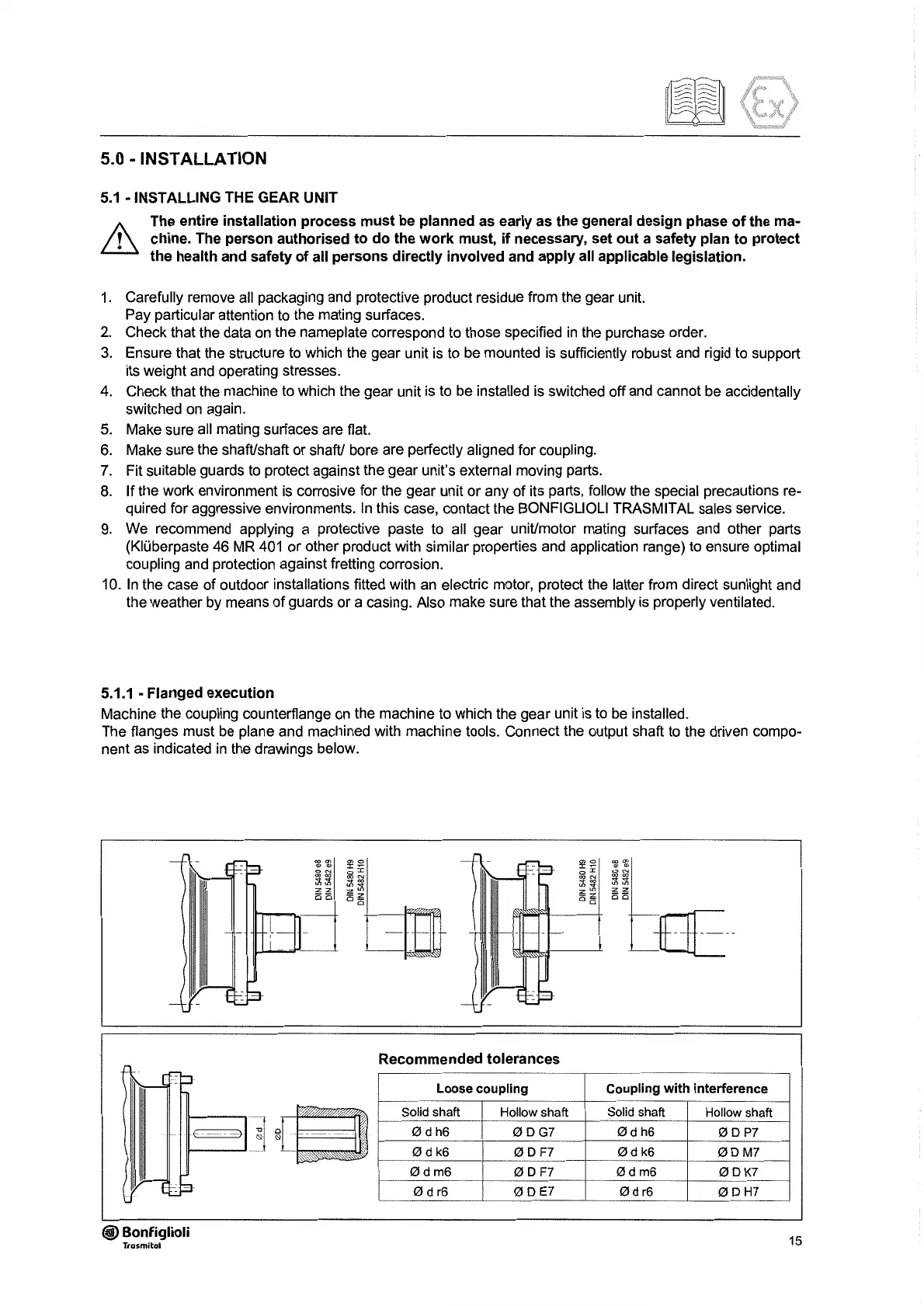
5.1.1
• Flanged execution
Machine the coupling counterflange
on
the machine to which the gear unit is to
be
installed.
The flanges must
be
plane and machined with machine tools. Connect the output shaft
to
the driven compo-
nent
as
indicated
in
the drawings below.
Recommended tolerances
Loose coupling Coupling
with
interference
Solid shaft Hollow shaft Solid shaft
Hollow shaft
Ødh6
ØDG7
Ød
h6
ØDP7
Ød
k6
ØD
F7
Ød
k6
ØDM7
e
~>1g
'
Ødm6
ØD
F7
Ødm6
ØDK7
ød
r6
ØDE?
ød
r6
ØDH7
@ Bonfiglioli
Trasmitol
15
 Loading...


