Supplementary system components
6.5 CX32-2 controller extension
SIMOTION D4x5-2
Manual, 02/2012
119
Position of the connector
The X122 connection is on the front side of the CX32-2 at the top, see appropriate figure in
Section Overview of interfaces (Page 116).
Conne
ction and circuit diagram
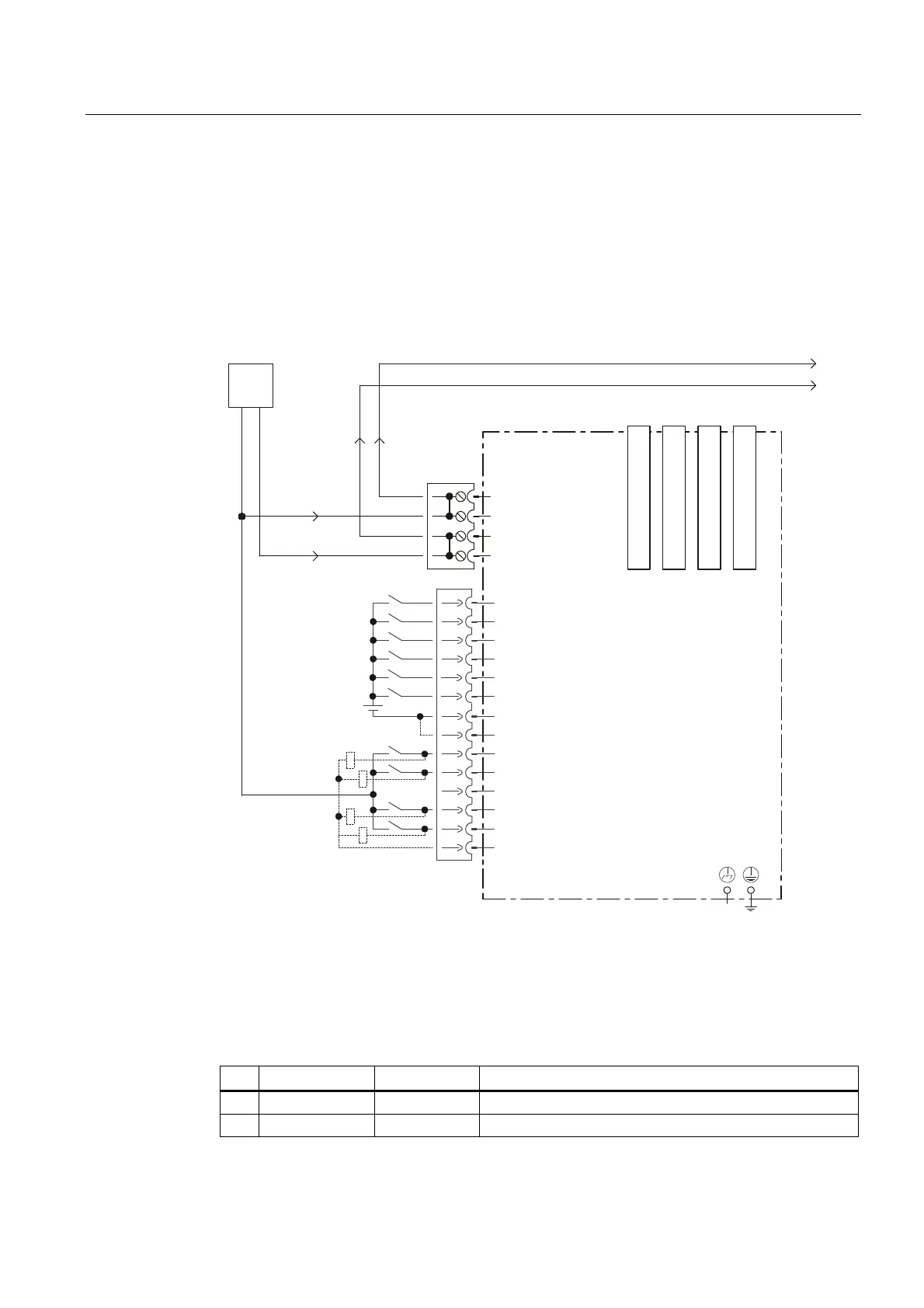
The following figure shows the schematic diagram and the connection of the digital I/Os on
the CX32-2 and the associated external power supply.
-XPSHURSHQHOHFWULFDO
LVRODWLRQIRUGLJLWDOLQSXWV',
&DQEHLQGLYLGXDOO\
SDUDPHWHUL]HGDVLQSXWRXWSXW
([W
&;FRQWUROOHUH[WHQVLRQ
0
0
','2
','2
','2
0
0
',
',
',
',
','2
;
',
',
; ; ; ;
;
0
0
0
0
9
0
0
9
'5,9(&/L4%XFKVH
'5,9(&/L4%XFKVH
'5,9(&/L4%XFKVH
'5,9(&/L4%XFKVH
Figure 6-13 Digital I/Os connection diagram
Interface assignment of X122
Table 6- 23 Digital I/Os X122
Pin Designation
1)
Signal type
2)
Information
1 DI 0 I Digital input 0
2 DI 1 I Digital input 1