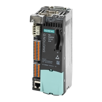
Do you have a question about the Siemens SIMOTION D425-2 and is the answer not in the manual?
Overview of the manual's content and its applicability.
Information on where to find additional support and resources online.
Frequently asked questions and answers for common issues.
General safety precautions and warnings for operating the equipment.
Safety guidelines specific to the SIMOTION D4x5-2 unit.
Provides a general understanding of the SIMOTION D system architecture and its components.
Details the various hardware and software components of the SIMOTION D system.
Information on the usage, function, and characteristics of the CF card.
Explains the machine-readable identification format used on SIMOTION D components.
Describes the location and function of front panel controls and indicators.
Details the function of switches, buttons, and displays for device operation.
Explains the meaning and function of the device's status indicators.
Lists and describes all available interfaces on the SIMOTION D4x5-2 unit.
Information on connecting components using the DRIVE-CLiQ serial interface.
Details the PROFINET IO interface capabilities and connections for the D4x5-2 DP/PN.
Properties and wiring of the digital input/output connectors.
Information on connecting to industrial Ethernet networks.
Details the PROFIBUS DP interface characteristics and assignments.
Information on using USB interfaces for device upgrades.
Specifies environmental conditions for shipping and storing the device.
Outlines permissible ambient conditions for device operation and use.
Provides physical dimensions and weight specifications for the device.
Details the power supply requirements and specifications.
Information on memory, PLC/motion control, and communication capabilities.
Technical specifications for the CF card used for storage.
Properties and functions of the integrated real-time clock.
Visual representation of the physical dimensions for D425-2 and D435-2 models.
Visual representation of the physical dimensions for D445-2 and D455-2 models.
Information on obtaining CAD data and circuit diagrams for system design.
Illustrates how supplementary system components connect to the main unit.
Details the functions, installation, and replacement of the fan/battery module.
Information on the TB30 terminal expansion module, its interfaces, and safety.
Technical details and overview of the CBE30-2 communication board.
Overview of the CX32-2 controller extension module and its capabilities.
Lists available parts and accessories for the SIMOTION D4x5-2.
Covers CE marking, EMC, and cULus approvals.
Notes specific to the SIMOTION D4x5-2 regarding EMC and installation.
Defines Electrostatic Sensitive Devices (ESDs) and potential damage.
Outlines essential steps for preventing electrostatic discharge.
| Product type designation | SIMOTION D425-2 |
|---|---|
| Control Unit Category | Control Unit |
| Power Supply | 24 V DC |
| Interfaces | Ethernet |
| Communication Interfaces | PROFIBUS, PROFINET, Ethernet |
| Operating Temperature | 55 °C |


 Loading...