Interfaces
4.4 Digital inputs/outputs
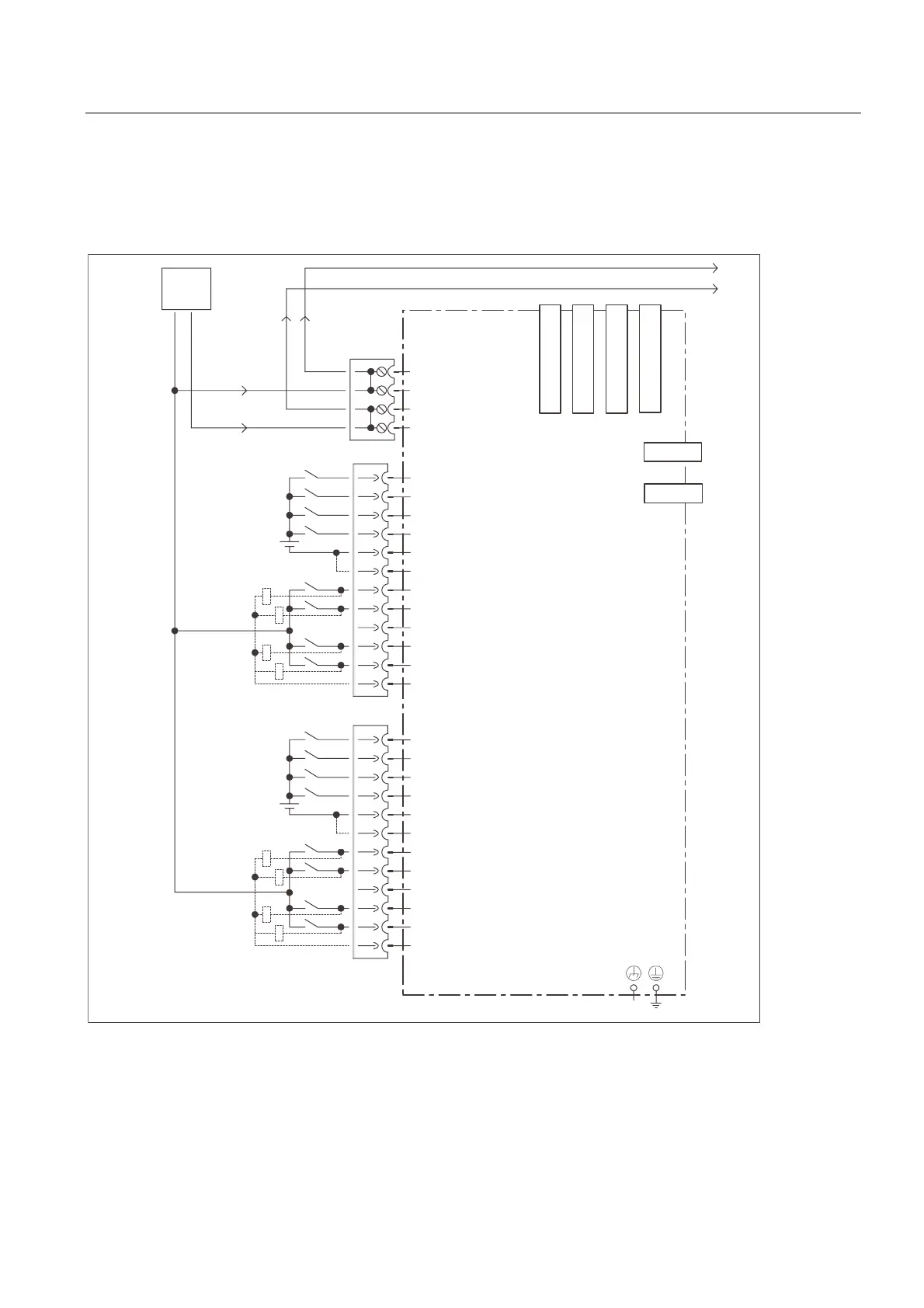
Wiring and block diagram for SIMOTION D using SIMOTION D435 as an example
The following figure shows the wiring diagram and the block diagram of the digital inputs and
digital inputs/outputs of the SIMOTION D435.
0
;;;;
;
0
',
;
',
',
',
0
0
','2
','2
','2
','2
0
0
',
;
',
',
',
0
0
','2
','2
','2
','2
0
0
9
0
;
0
0
0
;
([WHUQDO
9
'5,9(&/L4VRFNHW
'5,9(&/L4VRFNHW
'5,9(&/L4VRFNHW
'5,9(&/L4VRFNHW
6,027,21'
352),%86
352),%86
,QSXWVRXWSXWVPXVWEH
VKLHOGHG
-XPSHURSHQHOHFWULFDOLVRODWLRQ
IRUGLJLWDOLQSXWV',
&DQEHSDUDPHWHUL]HG
LQGLYLGXDOO\DVLQSXWRXWSXW
Figure 4-4 Wiring diagram and block diagram of the digital inputs/outputs
D4xx
Manual, 12.2004, 6AU1900-1AJ32-0BA0
4-7

 Loading...


