+
–
18
1
9
5
6
1
9
5
6
2
1
14
15
16
17
2
1
3
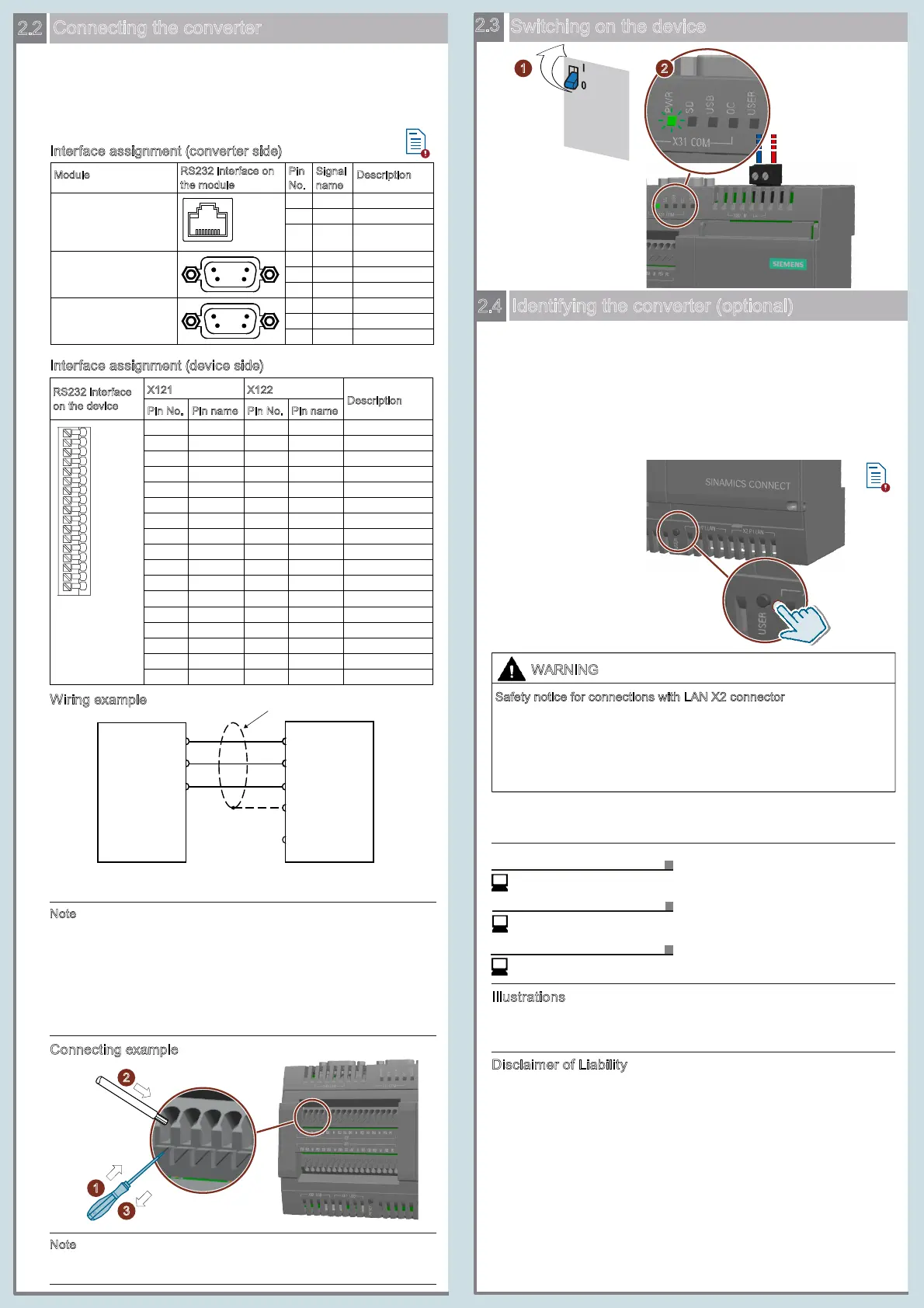
Switching on the device
9 V DC
to 36 V DC
Power
Supply
Wiring example
Connecting example
Improper connection might cause high voltages. The LAN X2 connector
is designed for connection to a Local Area Network “Environment A”
according to IEEE802.3 or "Environment 0" according to IEC TR 62102
only.
• Do not connect the LAN X2 connector directly to the telephone
network or a WAN (Wide Area Network).
Safety notice for connections with LAN X2 connector
WARNING
Disclaimer of Liability
This document contains illustrations of the described devices and
accessories. The illustrations may deviate from the particularities of the
delivered device and accessories.
The SINAMICS CONNECT supports port modes of "Auto" and
"Manual" which you can set via the SINAMICS CONNECT Web
server. For more information, see Section "Configuring ports" in the
SINAMICS CONNECT Operating Instructions.
• Auto (default): Keep pressing the USER button for at least 1
second to identify the converter at the port, or wait (up to 5
minutes) for the device to identify the converter.
• Manual: You must set the basic parameters of the converter
manually via the Web server.
User documentation online
Central Technical Support
Service and spare parts
I
llustrations
Connecting the converter
Interface assignment (converter side)
You can connect a SINAMICS CONNECT device to one of the
following converters via the RS232 interface on the converter
specific optional module or Control Unit:
• SINAMICS V20
• SINAMICS G120 series (G120D excluded)
• MICROMASTER 440
Interface assignment (device side)
Power
On
We have reviewed the contents of this publication to ensure consistency
with the hardware and software described. Since variance cannot be
precluded entirely, we cannot guarantee full consistency. However, the
information in this publication is reviewed regularly and any necessary
corrections are included in subsequent editions.
Identifying the converter (optional)
Siemens AG
Digital Factory
Motion Control
Postfach 31 80
91050 ERLANGEN
Germany
To achieve better EMC performance, Siemens recommends that you
observe the following when connecting the device:
• Use the shielded cable for RS232 communication between the
converter and the device.
• Do not connect the device to the ground via the PE terminal (pin 1 at
X121, pin 17 at X122).
• Route the signal cables and the power cables separately in different
cable conduits.
Siemens recommends that you use the signal cable with a length less
than 3 m.
Note
Note
Cable shield
SINAMICS V20
BOP Interface Module
SINAMICS CONNECT
RJ45 connector
socket
RS232 interface
o
n
the
device
X
121 X122
D
escription
1 17
Module
RS232 interface on
the module
Description
for SINAMICS V20
SINAMICS G120 series
(G120D excluded)
module for
MICROMASTER 440
...
...
1
2
3 M
RX1
PE1
PE
TX1
GND
TXD
RXD
15
16
14
1
X121
17
2.3
2.4
https://support.industry.siemens.com/sc/ww/en/sc
© Siemens AG 2018. All rights reserved
A5E45421417-002 10/2018
https://support.industry.siemens.com
https://support.industry.siemens.com/cs/ww/en/ps/25436/man
2.2
(≤ 12 N)

 Loading...


