Do you have a question about the Siemens SITOP PSU8200 3ph and is the answer not in the manual?
Emphasizes safe operation, qualified personnel, and proper installation procedures to prevent injury.
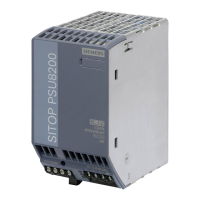
Introduces the SITOP PSU8200 3ph as a primary-clocked power supply with electronic regulation and LED indicators.
Details line input, output terminals, and signaling contacts with connection data for different models.
Describes LED indicators and signaling contacts for operating status and faults.
States the device is built-in and must be installed in a housing/cabinet by qualified personnel.
Explains how to mount the device on a standard mounting rail and how to remove it.
Specifies requirements for installing devices in hazardous zones, requiring a distribution box with IP54 or higher.
Describes standard vertical mounting on DIN rails for cooling and required clearances.
Shows derating curves for output current based on ambient temperature for standard mounting.
Warns about electric shock and the need to switch off power before installation or maintenance.
Details the connection to a 3-phase AC line supply, including required protection devices.
Specifies required circuit breakers and protective conductor connections for line supply.
Explains connecting to loads via output terminals and grounding considerations.
Details galvanic isolation, protection class, degree of protection, and leakage current.
| Output Voltage | 24 V DC |
|---|---|
| Protection Class | IP20 |
| Output Current | 40A |
| Power | 480 W |
| Operating Temperature | -25 to +70 °C |


 Loading...