Siemens Building Technologies / HVAC Products 74 319 0325 0 b 12.2002 3/4
Geräteschaltpläne
Internal diagrams
Schéma de raccordement
Kopplingsschema
Inwendige aansluitschema's
Morsettiera
Kythentäkaavio
Esquema de conexionado
Tilslutningsdiagram
Schemat połączeń
Vnitřní zapojení
Kapcsolási sémák
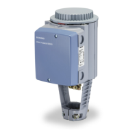
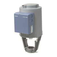
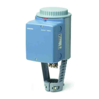
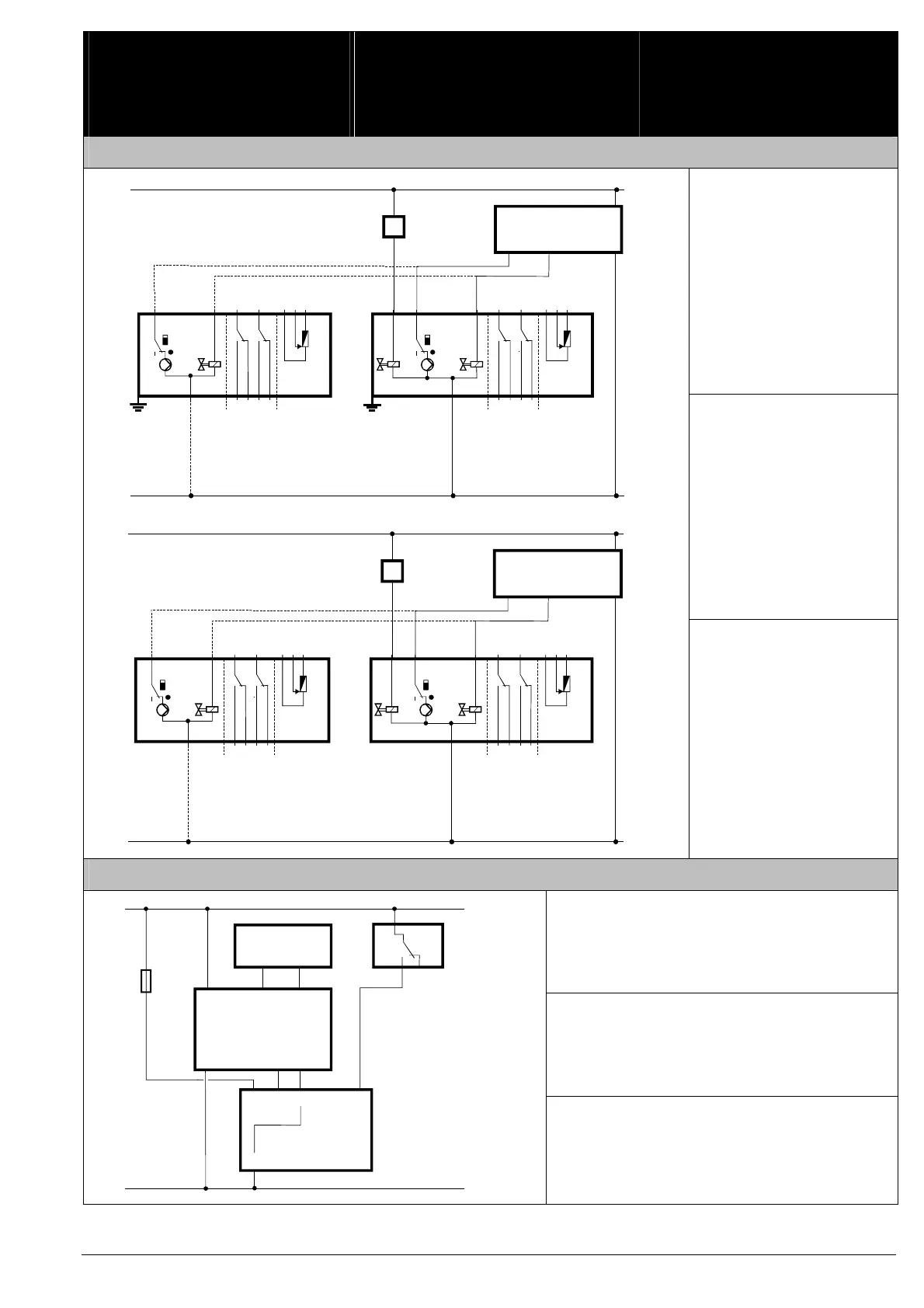
SKD32... / SKD82...
Betriebsmittel:
F1 Temperaturbegrenzer
N1 Regler
Y... Stellantriebe
C1/2 Umschalter
Cm1 Endschalter
ASC9.3 Hilfsschalterpaar
ASZ7.3... Potentiometer
Anschlussklemmen:
L Phase
N Nullleiter
G Systempotential
G0 Systemnull
Y1 Stellsignal «öffnen»
Y2 Stellsignal «schliessen»
21 Notstellfunktion
Field devices:
F1 Temperature limiter
N1 Controller
Y... Actuators
C1/2 Change-over switch
Cm1 End switch
ASC9.3 Dual auxiliary switches
ASZ7.3... Potentiometer
Connection terminals:
L Phase
N Neutral conductor
G System potential
G0 System neutral
Y1 Control signal «Open»
Y2 Control signal «Close»
21 Spring return function
Y1 Y2
01815
N1
L
N
AC 230 V
Y1 Y2 3 3 a b c
100 %
0 %
100 %
0 %
N4545
Cm1
c1 c2
ASC9.3 ASZ7.3...
Y1 Y2 3 3 a b c
100 %
0 %
100 %
0 %
N4545
Cm1
c1 c2
ASC9.3 ASZ7.3...
21
n
T
F1
Y1
SKD32.51SKD32.50
Y2
SKD32.21
Y1 Y2
01814
N1
G0
G
AC 24 V
Y1 Y2 3 3 a b c
100 %
0 %
100 %
0 %
G 4545
Cm1
c1 c2
ASC9.3 ASZ7.3...
Y1 Y2 3 3 a b c
100 %
0 %
100 %
0 %
G4545
Cm1
c1 c2
ASC9.3 ASZ7.3...
21
n
T
F1
Y1
SKD82.51 (U)SKD82.50 (U)
Y2
Équipement:
F1 Limiteur de température
N1 Régulateur
Y... Servomoteurs
C1/2 Contact inverseur
Cm1 Contact de fin de course
ASC9.3 Paire de contacts auxiliaires
ASZ7.3... Potentiomètre
Bornes de raccordement:
L Phase
N Neutre
G Potentiel du système
G0 Zéro du système
Y1 Signal de commande «ouvrir»
Y2 Signal de commande «fermer»
21 Fonction de retour à zéro
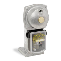
SKD62... / SKD60
Betriebsmittel:
B1 Fühler
F1 Temperaturbegrenzer
N1 Regler
Y1 Stellantrieb
Anschlussklemmen:
G Systempotential
G0 Systemnull
Y Stellsignal
M Messnull (= G0)
U Stellungsanzeige
Z Zwangssteuerung
Field devices:
B1 Sensor
F1 Temperature limiter
N1 Controller
Y1 Actuator
Connection terminals:
G System potential
G0 System neutral
Y Control signal
M Measuring neutral (= G0)
U Position indication
Z Override input
GB1M
G0
Y1
N1
GM
Z
G0
Y1
Y
U
BM
01802
B1
G (SP)
G0 (SN)
AC 24 V
F1
32
1
M
Fuse
Équipement:
B1 Sonde
F1 Limiteur de température
N1 Régulateur
Y1 Servomoteur
Bornes de raccordement:
G Potentiel du système
G0 Zéro du système
Y Signal de commande
M Zéro de mesure
U Indication de position
Z Commande forcée
 Loading...