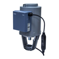
Do you have a question about the Siemens ACVATIX SKB Series and is the answer not in the manual?
| Brand | Siemens |
|---|---|
| Model | ACVATIX SKB Series |
| Category | Controller |
| Language | English |
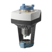
Diagrams illustrating the working principle of actuators in closed and open states with numbered components.
Application of Siemens actuators for valves in HVAC systems, specifying valve types and stroke.
Details on control signals for SKB32/SKB82 3-position and SKB62/SKB60 Y-positioning signals.
Information on connecting frost protection thermostats and monitors to SKB actuators.
Configuration via DIL switches for SKB60, covering direction, fail-in-place, signal, and flow characteristics.
Configuration via DIL switches for SKB62UA, covering direction, sequence control, signal, and flow characteristics.
Explanation of the spring-return function and its operation during power failure or signal loss.
Mandatory calibration steps for SKB60, SKB62, SKB62/MO actuators for initial commissioning.
Guide to interpreting the dual-colored LED for operational status, calibration, errors, and troubleshooting for SKB60/SKB62 actuators.
Overview of different operating modes for the override control input Z on SKB60 and SKB62 actuators.
Explanation of 'direct acting' and 'reverse acting' modes for SKB60 and SKB62UA actuators.
Configuration details for stroke limit control and sequence control using rotary switches on the SKB62UA actuator.
Setting the operating range for frost protection monitors QAF21/QAF61 via rotary switches on the SKB62UA.
Details on available accessories like stem heaters, stroke inverters, switches, and potentiometers with their specifications.
Lists of compatible 2-port Siemens valves (VVF) for actuator mounting, with technical data.
Lists of compatible 3-port Siemens valves (VX) for actuator mounting, with technical data.
Reference to mounting instructions, standard settings, communication profiles, and download links.
Essential safety advice covering national regulations, spring return, housing, and burn hazards.
Guidance on safety limiters, hot device parts, insulation, and controller integration for safe operation.
Instructions for physical mounting, electrical connections, and initial system commissioning of the actuators.
Procedure for operating the actuator in automatic mode using the manual adjustment knob and crank.
Instructions for manual operation and safety precautions when servicing the actuator, including burn and injury risks.
Information on actuator repair, responsible disposal as electronic waste, and warranty terms.
Detailed specifications for power supply, operating voltage, positioning signals, input impedance, and hysteresis.
Specifications for positioning time, spring-return time, positioning force, nominal stroke, and permissible medium temperature.
Details on enhanced functions like direction selection, stroke/sequence control, signal addition, and Modbus RTU communication for specific models.
Specifications for electrical connections, environmental operating conditions, protection classes, and compliance with directives/standards.
Physical weight, housing materials, and specifications for various compatible accessories like switches and potentiometers.
Internal connection diagrams for SKB32 and SKB82 series actuators, showing wiring for positioning and spring-return functions.
Wiring diagrams for SKB6, SKB62, SKB62U, SKB62UA actuators, detailing signal connections.
Terminal assignments and Modbus RTU connection cable details for SKB6 and SKB62/MO actuators.
Electrical connection diagrams for SKB32.51 and SKB32.50 actuators, illustrating power and signal wiring.
Electrical connection diagrams for SKB82.51/SKB82.50 actuators, illustrating power and signal wiring with system potential/neutral.
Electrical connection diagrams for SKB60 and SKB62 series actuators, showing signal inputs and frost protection connections.
Wiring diagram for the SKB62/MO Modbus RTU actuator, detailing communication and safety limiter connections.
Detailed dimensional drawings for the actuator and the ASK51 stroke inverter, with measurements in mm.






 Loading...